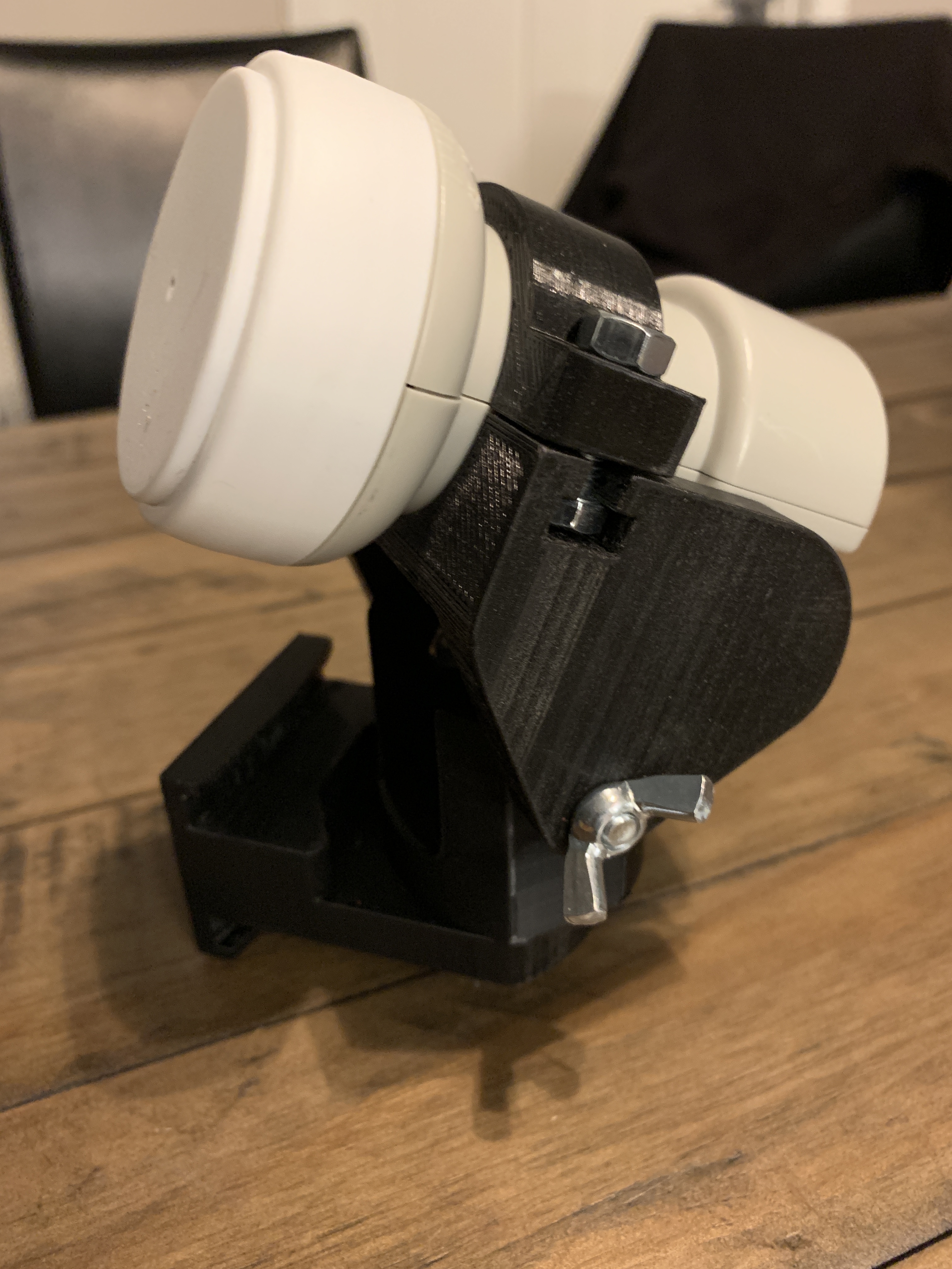
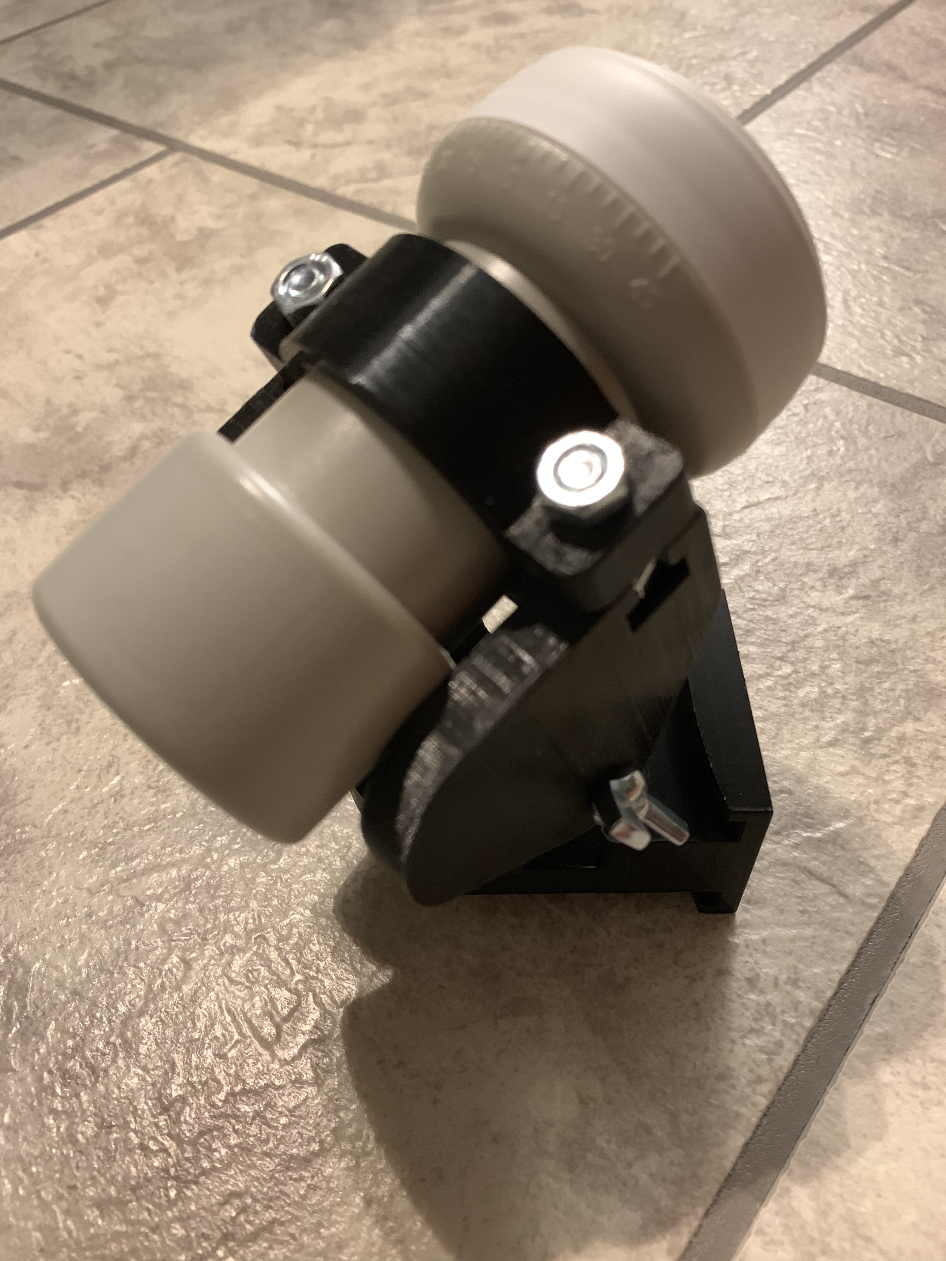
Hay that’s nice! Looks like it works like it should.
Sadly i didn’t have time yet to print every part of it, but you have one for testing what is more important to me.
Any Problems or things that should be changed?
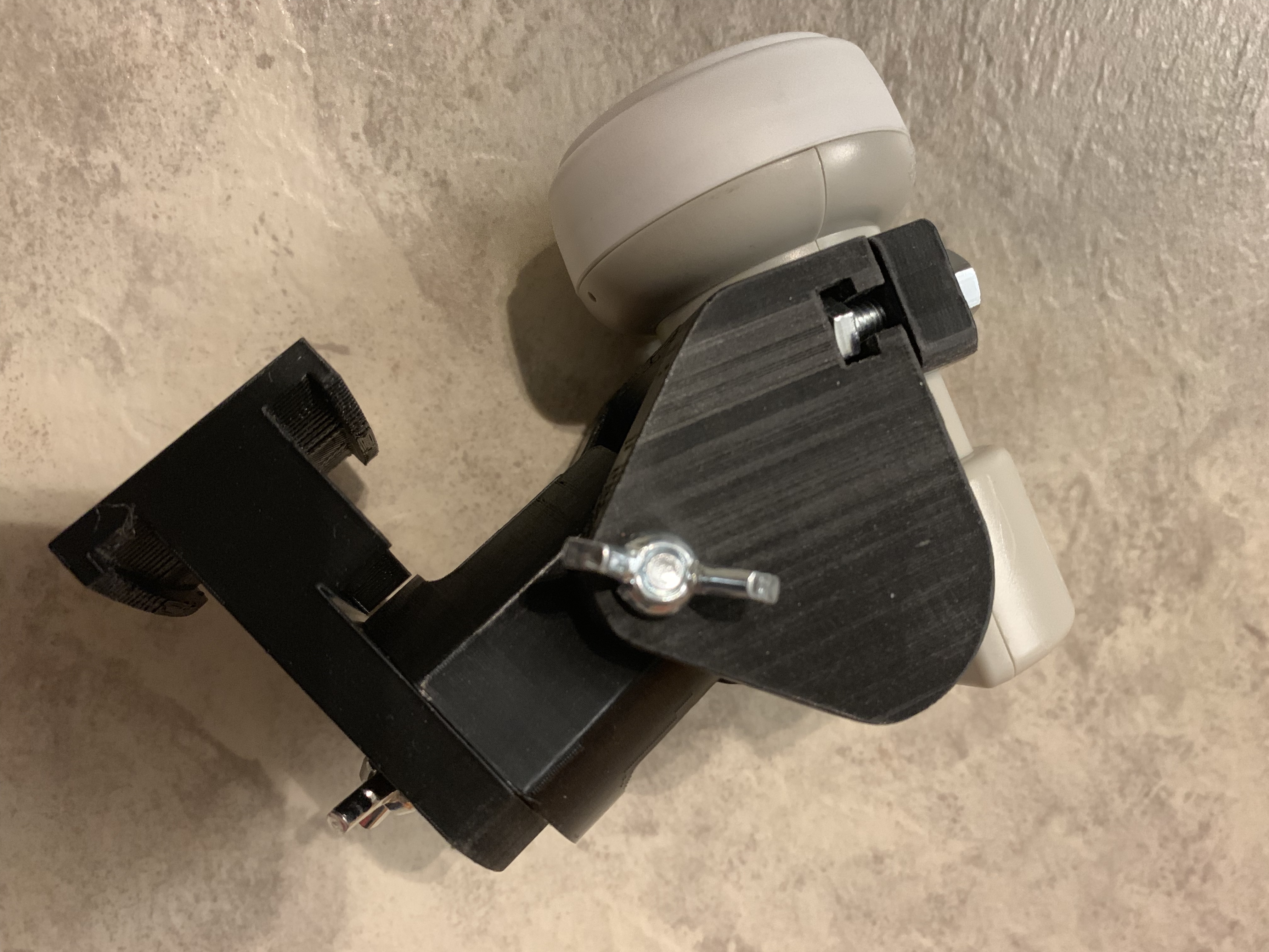
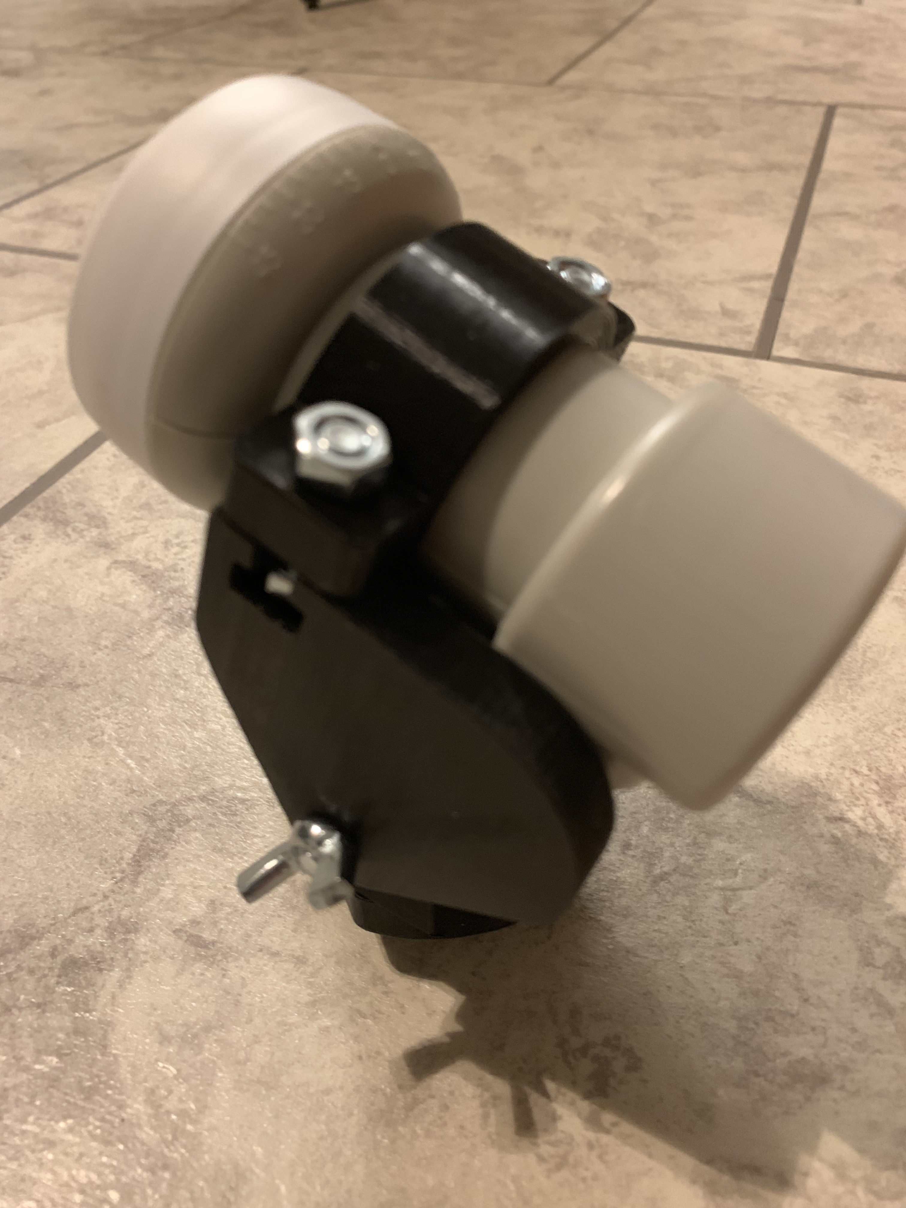
Do you get the Signal cable onto the LNB still without blocking Elevation adjust?
Does it hold it’s Position after fastening the wingnuts?
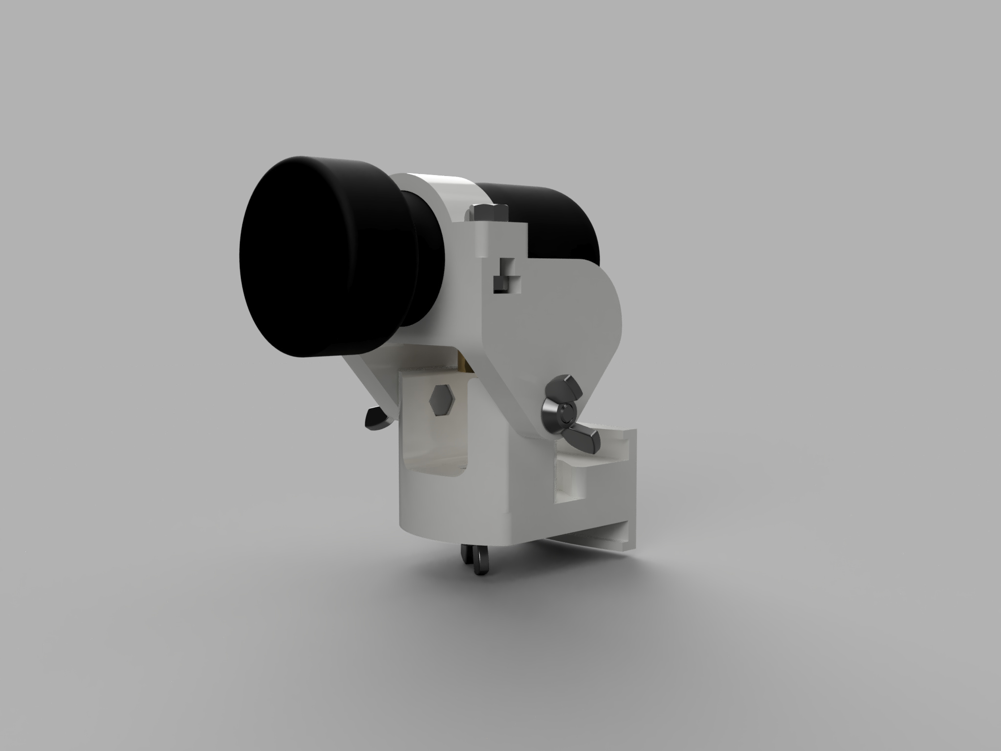
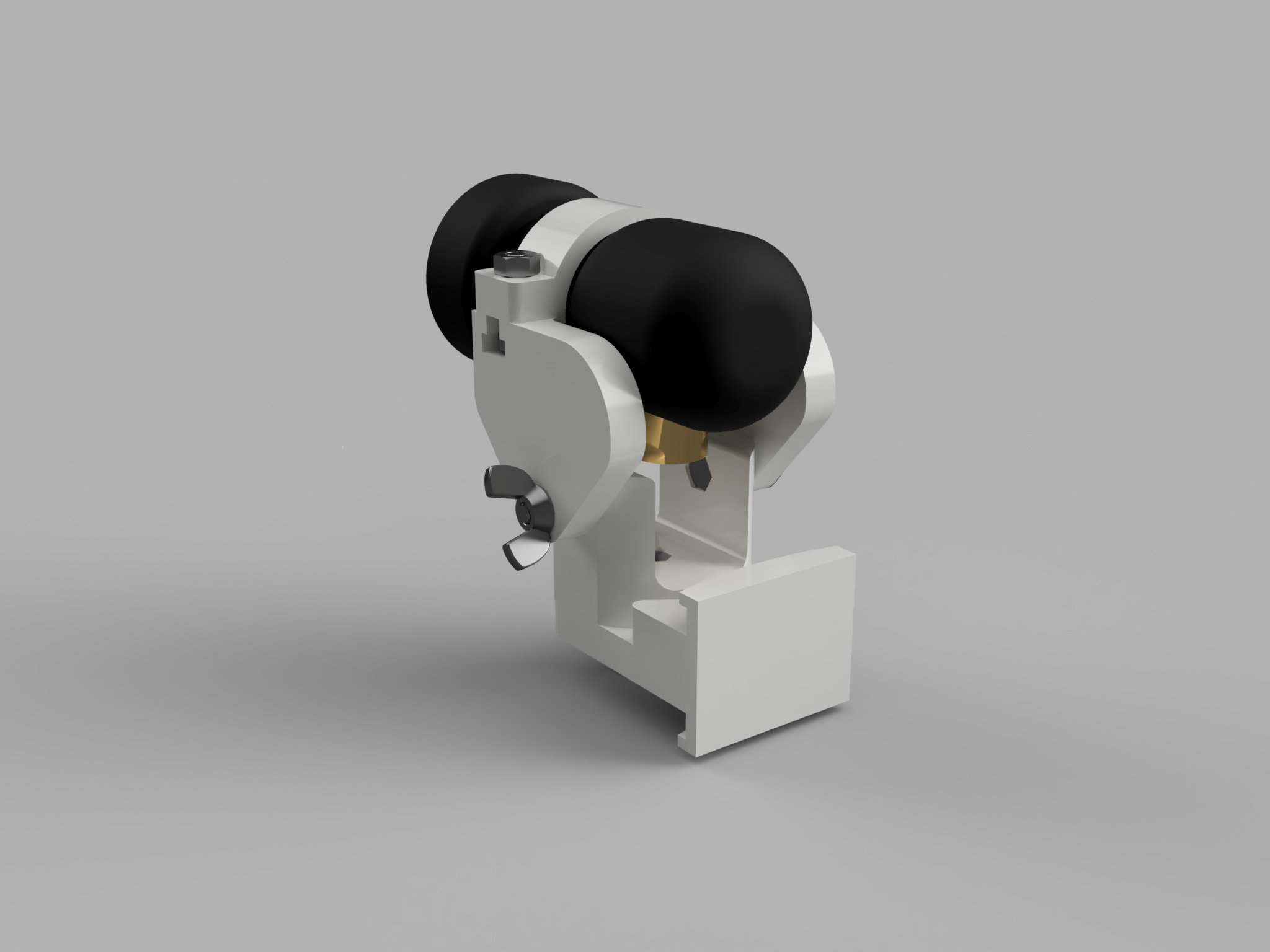
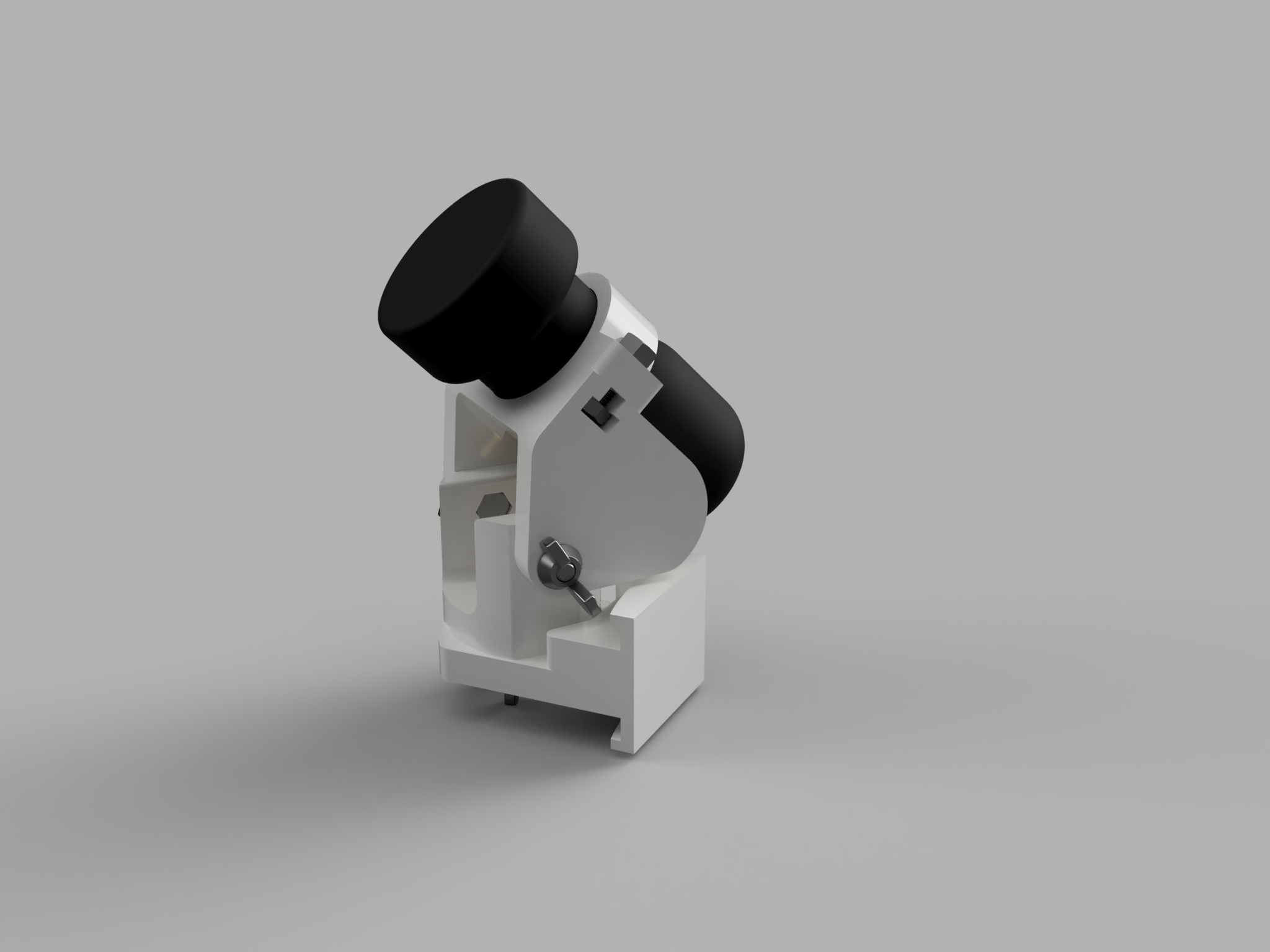
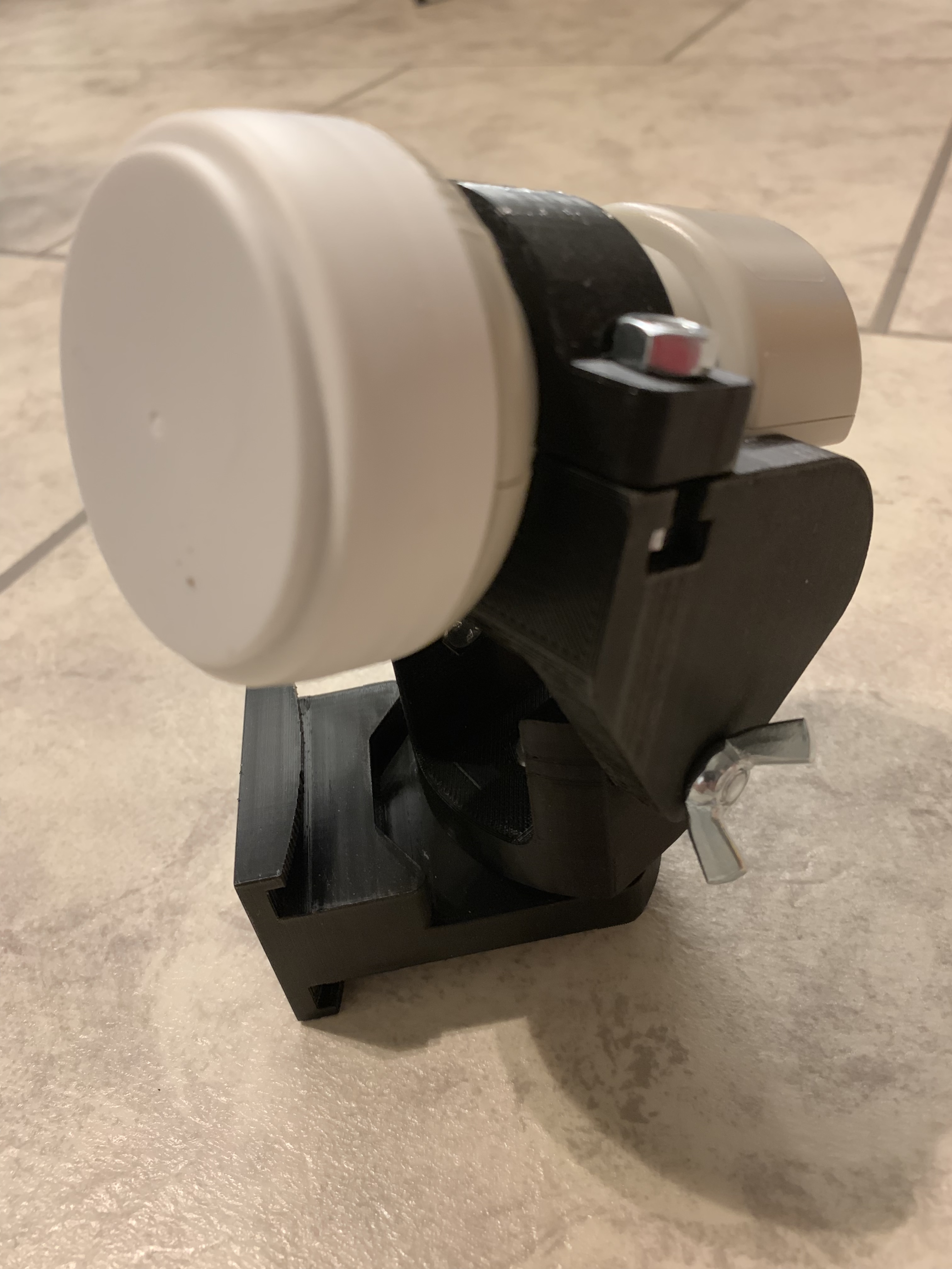
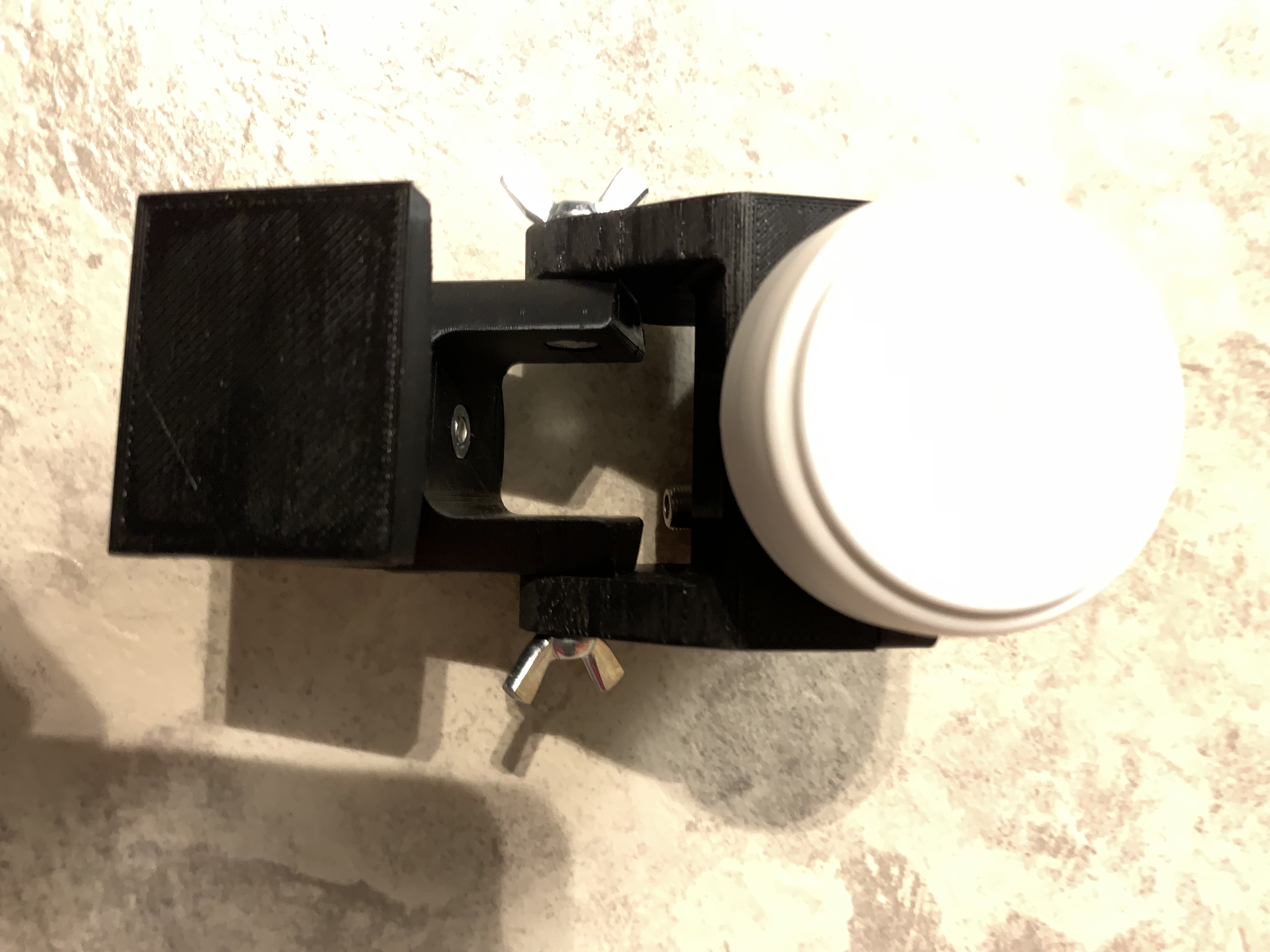
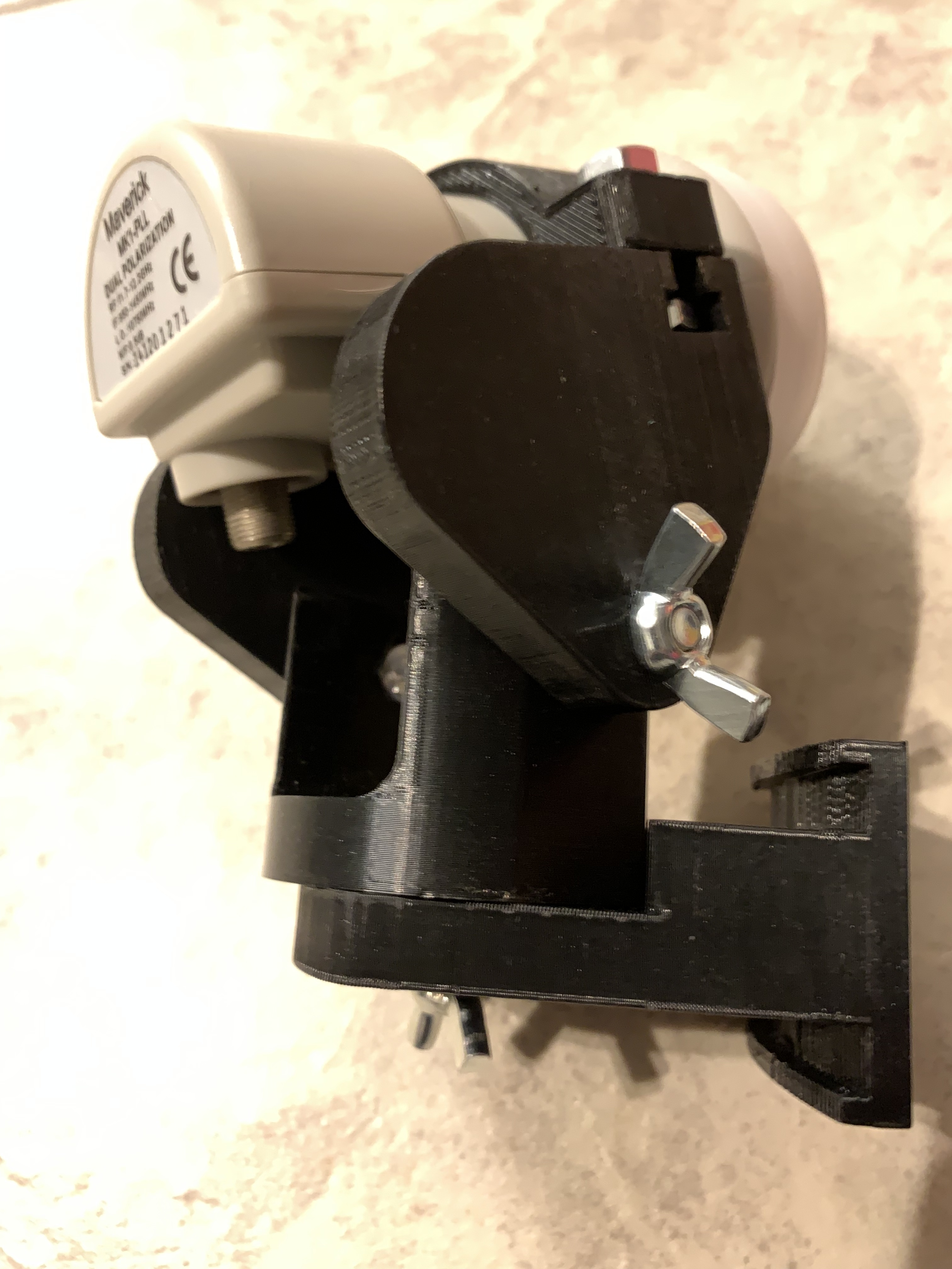
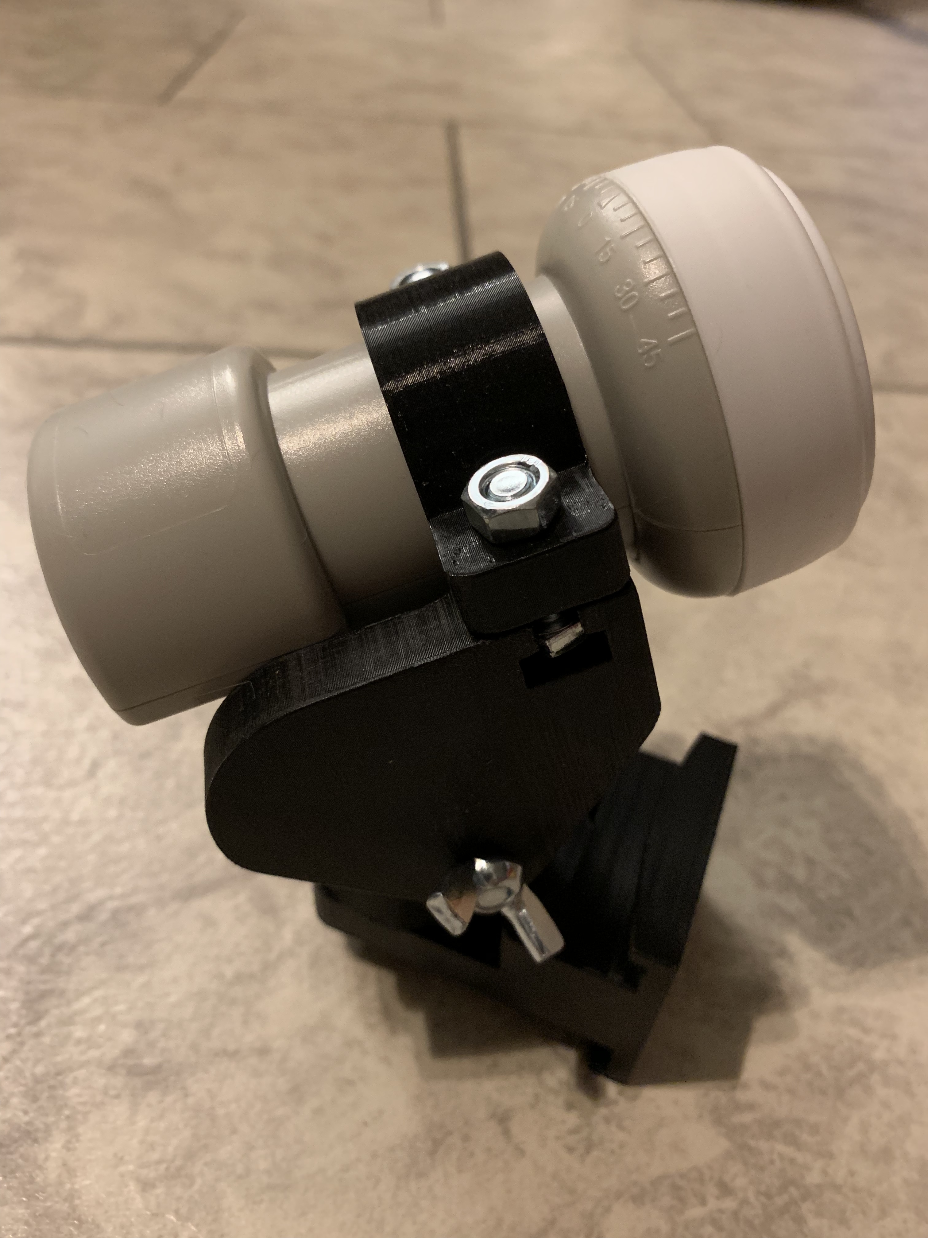
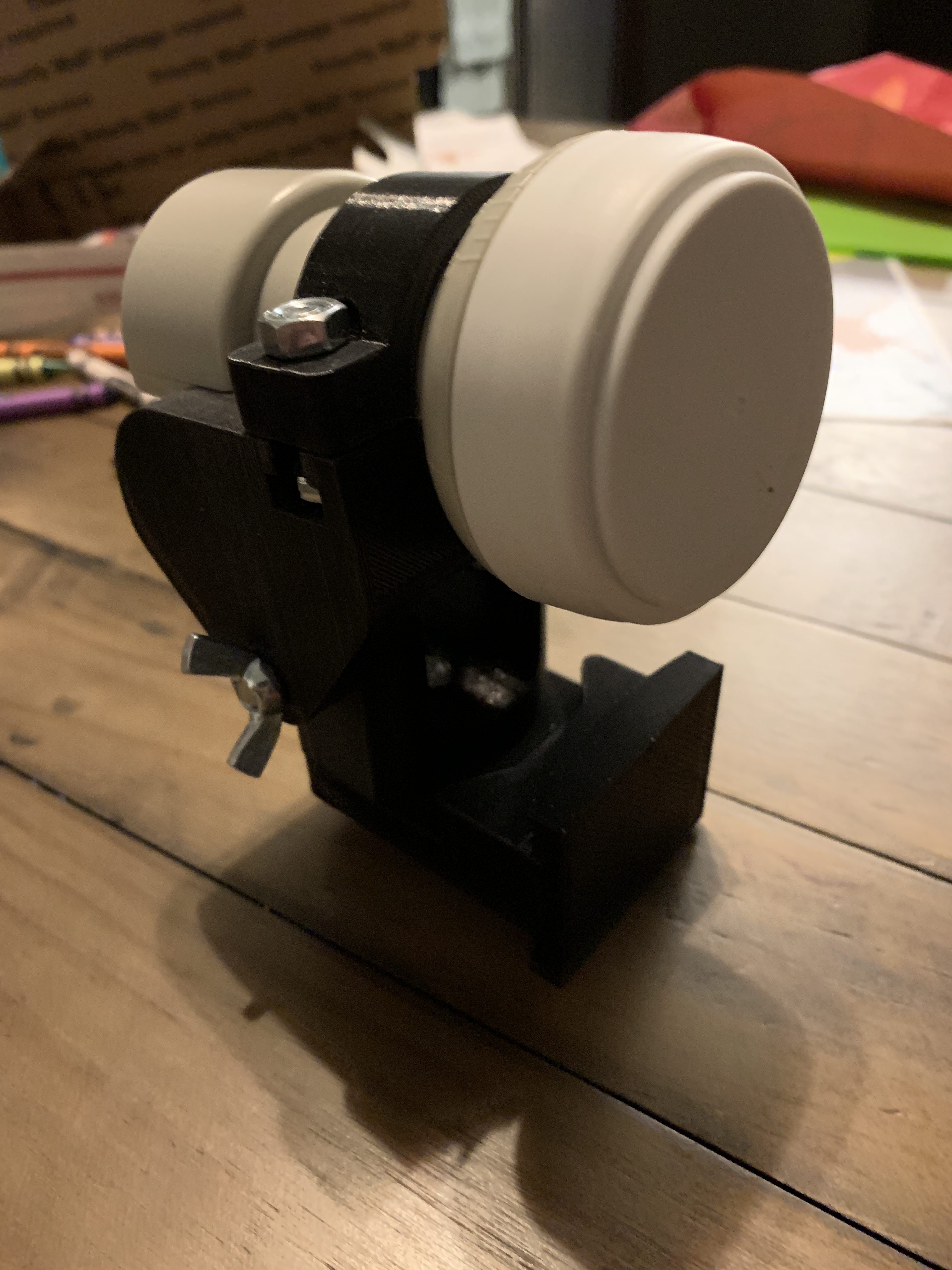
Yes, it works perfectly. There are few minor points worth consideration.
The neck of the assembly might need to be extended vertically so that the wing nuts don’t hit the flange.
The flange could use four holes for attaching directly to a wall or board.
It would be great if the assembly could stand on its own in all orientations; that would require the flange to have two legs added toward the front of the assembly.
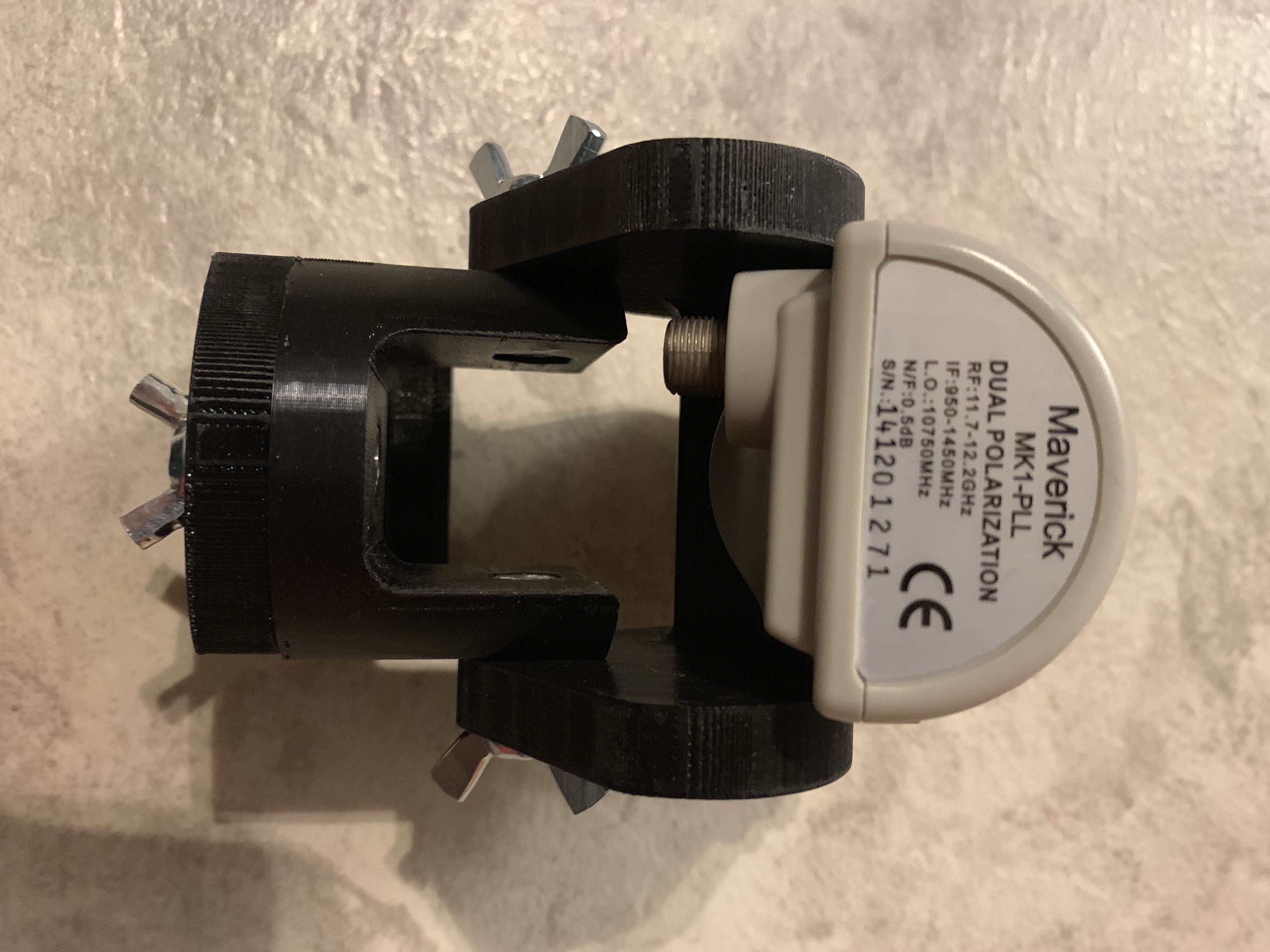
The ears of the assembly (part that sits on the neck) don’t allow the MK1 to fully rotate/adjust skew, due to the off-center placement of the F-connector on the MK1. Another LNB I have with a centered F-connector rotates just fine.
But all in all, the assembly works exactly as it was supposed to. I am impressed!
It’s an open source design that can be printed and used for existing, standard LNBs. No harm in that.
The new antenna is not a new design. We couldn’t get the required performance from the patch arrays, so we’ll be using another LNB, which will be roughly the same size as the MK1, but without the casing, since everything will be inside of a dome.
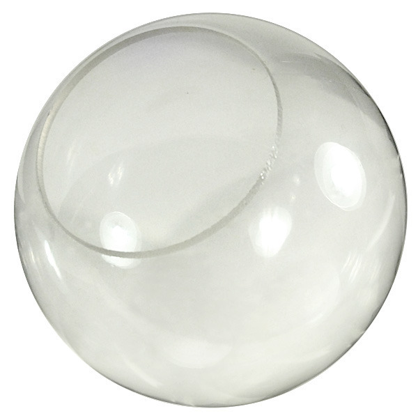
Interesting - - that said, I’m going to proceed with a new enclosure for a portable unit that I’ve been working on (but put on hold pending the patch concept). I got the idea from a 6 inch diameter Mova Globe (www.movaglobes.com) I have which failed so I could take it apart.
It is a Dreamcatcher mounted underneath (sandwiched) with the LNB, then installed in the clam shell sphere that sits on top of a small tripod stand allowing rotation of the sphere for antenna pointing. The touch screen is remoted by a short cable and mounted on the rear of the sphere so you can read it as you point. I haven’t decided to include a built in rechargeable power source, or run it off an external one. Here’s a conceptual picture illustrated with a basketball. The LNB is inside and points out the back side of the picture.
I am real curious on the next dreamcatcher details. The limited info is a dome enclosure.
Will the pcb be different. (I like only one antenna port, only one micro otg usb port, fewer led’s, jtag points or serial pins, second usb and hub support). Physically more robust, smaller, ???
Will it have lcd ? what is the power connection / requirements.
As another alternative, I’m thinking about using a clear plastic lamp post cover 8" in diameter with a 4 inch cutout hole that I will widen to fit the Dreamcatcher inside. All the equipment (DC, LNB, LiPo battery and charger) will be inside the globe.
However, what did you print it out of? PLA (cheapest material) does not do well in a UV drenched environment and has a very low meting point. Stuff I’ve made for my car such as brackets to hold my ham gear warp in the heat. I would suggest ABS at least.
Also, what print settings etc did you use? Infill %, layer height etc etc etc ?

 Ken
Ken