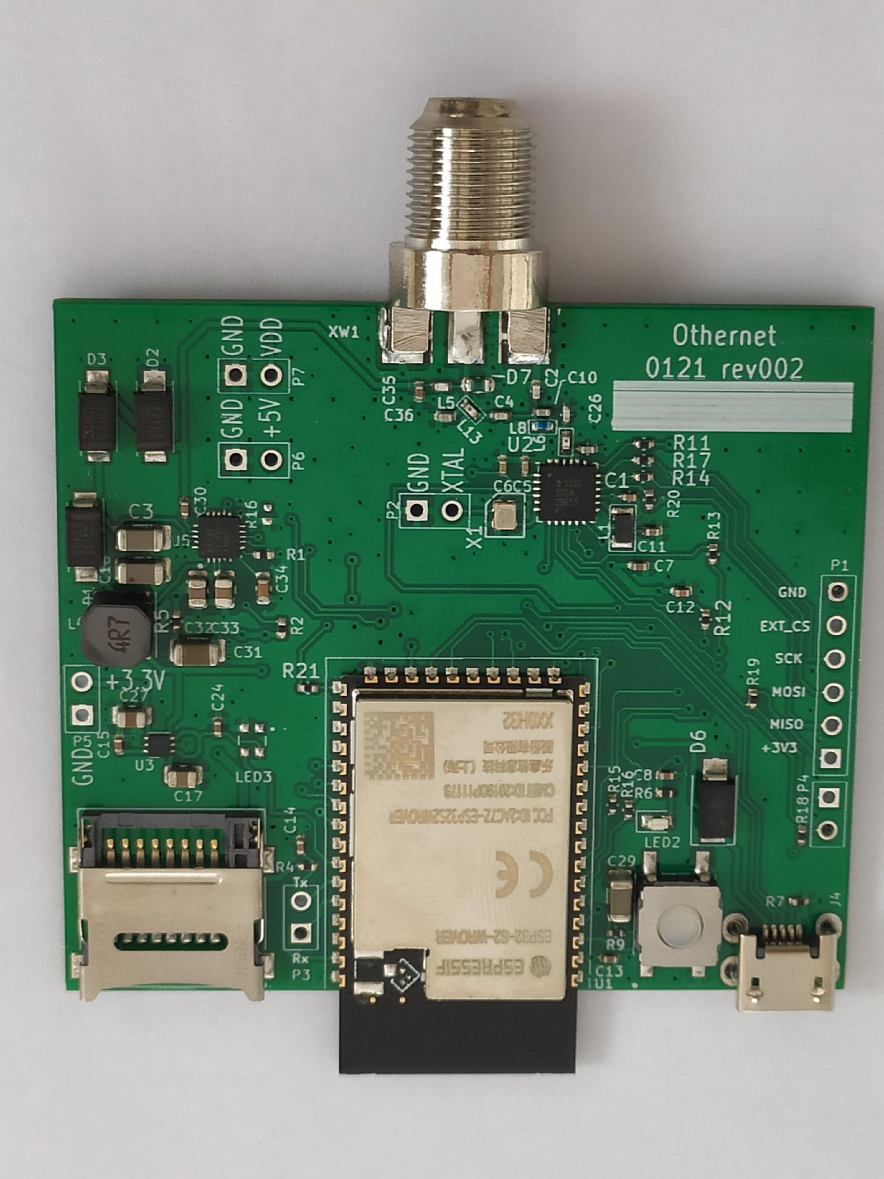
And here it is. The active components won’t change much, though the layout may still be condensed from the current 59mm x 52mm. Rather than a single-sided board, it’s possible for the board to be two-sided. A few more pins from the ES32 might be routed out. Other than that, it’s similar to what has been previously described.
Processor: Espressif ESP32-S2
Wifi: ESP32-S2
Diseqc IC: Texas Instruments TPS-65235
LoRa transceiver: SX1281
3.3V regulator: Microchip MIC5353YMT
And one green LED
The ESP32-S2 WROVER module includes a microstrip antenna for wifi, as well as 4 MB of storage. About 1 MB will be dedicated to the firmware and another 1 MB will be used for firmware updates. The firmware will almost assuredly grow in size to support new applications and also a more polished user interface. About 1 MB of storage will be set aside for receiving files, in the event that no microSD card is present. The firmware will be posted on Github next week, maybe sooner.
It’s a pretty simple board. I’m happy to answer questions about it, though there isn’t much more to tell.
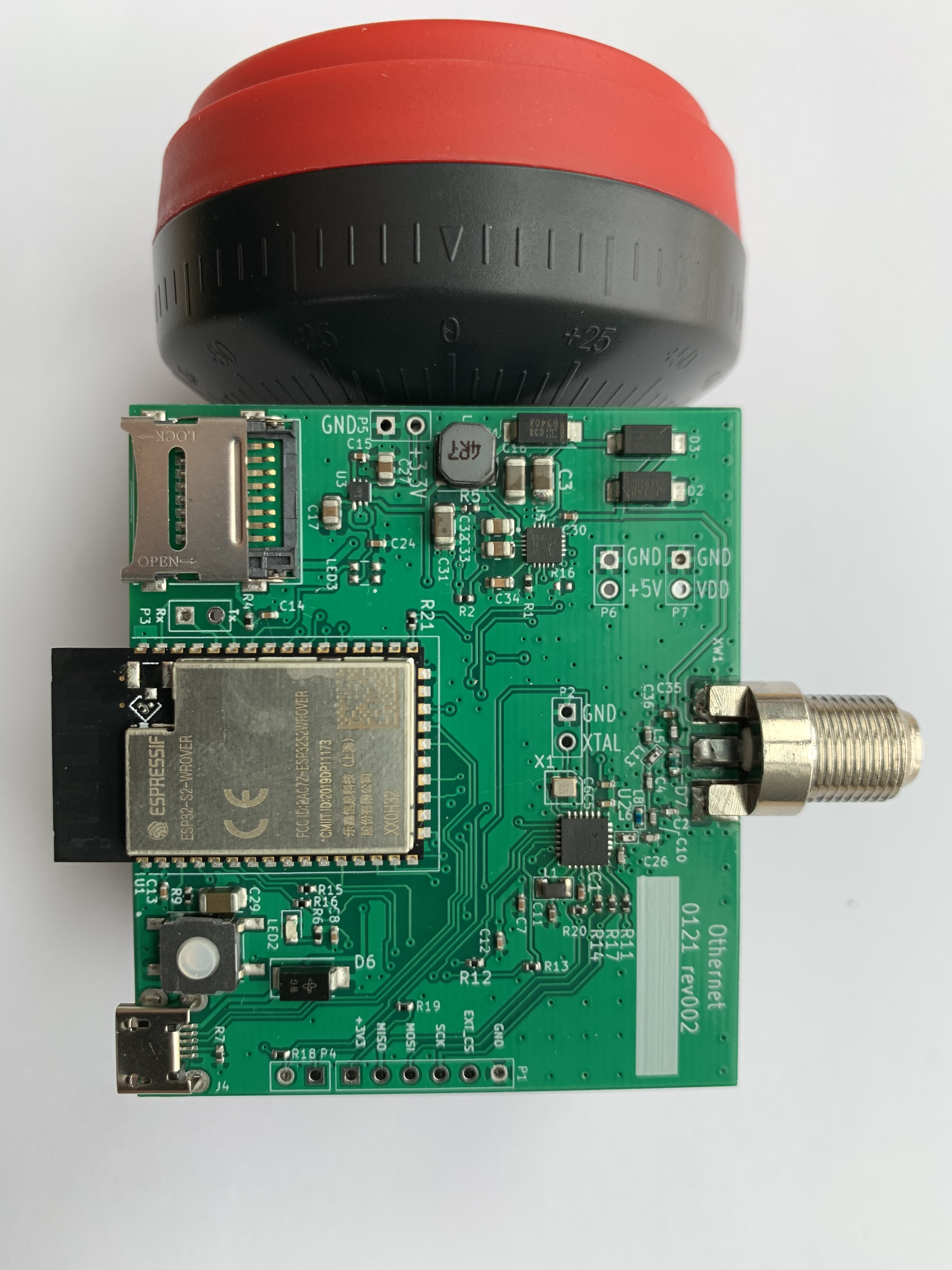
The F-connector will likely change so that the board sits parallel to the LNB. Both the LNB and Dreamcatcher will be placed inside of a waterproof housing (like a small jar). The front of the LNB will protrude so that the LNB can be optionally mounted on the bracket of a dish. For standalone reception (no dish), a small stand will be used to hold the LNB at the proper elevation angle. The entire housing will turn to allow for skew adjustments. A microUSB cable will connect through the rear of the housing. Sorry, no pictures of the housing yet. Very much a work in progress.
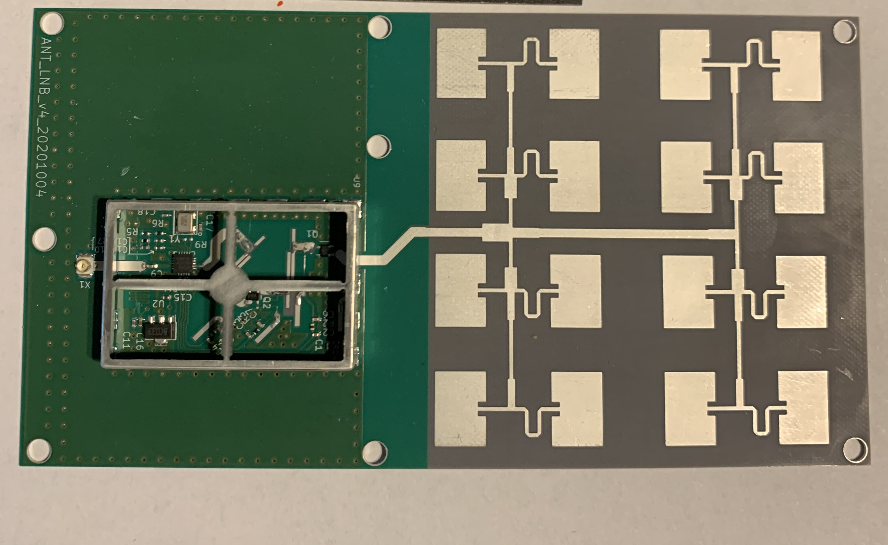
The LNB and Dreamcatcher inside of the housing will be Lantern. Someday, Lantern will be fully integrated into a single PCB. The picture below is a patch array with LNB. The Dreamcatcher components will be added to this in a future version. This is even more of a work in progress. No idea when the single board receiver will be finished.
Is the circuit board then totally supported by the type F jack? Will there be a size limit on the SD card, also why full size instead of micro SD (SDXC)? Is the power still supplied via the micro-USB jack? Are there yet projected release dates for the DC4 and for the Lantern with the patch antenna?
Inside of the housing, the board will not be totally supported by the F connector. This particular F connector will be replaced with a 90-degree connector.
It is a microSD card. The maximum size of microSD is 32GB.
Yes, power still comes over microUSB.
Nope, no projected dates. Just trying to make as much progress as quickly as possible.
Noted that this board is a 3.3v device. Have you addressed the input voltage issue, such as making it agile from 4.5 to 5.5 volts so that the average 5 volt consumer wall wart will be usable?
Is the patch antenna/lnb board available somewhere for purchase currrently?
The main module/SoC is a 3.3V device, but the voltage regulator is the Microchip MIC5353YMT, which has an input voltage range of 2.6V - 6V. Here’s the datasheet.
The integrated patch array-LNB is an Othernet design and is still experimental. I have received with it so I can verify real-world performance of the LNB. The tricky part to get right is the two-stage LNA. The design does provide sufficient LNA gain, but the radiation pattern of this 4x4 array is a little jagged, with the main lobe being too narrow. The antenna needs to be revised into a 2x2, which has a much smoother, more consistent radiation pattern.
So this new board is also going to require less power? Also does the software retain the ability to connect to another wifi network as the current skylark can?
Oddly, the power consumption is the same as Dreamcatcher 3.05. The ESP32 is very power hungry, which is strange since it’s running at a much lower speed. Yes, the software does retain the ability to connect to another wifi network. When the device is connected to a wifi network, it can still be accessed over its own wifi access point.
So presumably, we won’t see power problems as before with the older Dreamcatchers requiring us to to use more stable higher voltage RaspberryPi power supplies? Ken
Cute! Is there a reason why the power connector and antenna connector can’t be on the same side of the board? Also, what is the projection from under the main IC? I am looking at the obstacles to compact enclosure ideas, such as all the off-board projections being on one edge of the circuit board. Also there do not seem to be any through-board mounting holes?
Sorry for newbie question, but should I buy Dreamcatcher 3.05 or wait till 4.0? Whats the difference between them? How long Dreamcatcher 3.05 and the service will be supported?
Nice, the pigtail with a micro antenna connectotor still seems a good solution for future enclosure as you cau put the socket where you like. Agree a couple of hole are very useful to lock it by screw.
Very compact, tnx for the job
3.05 runs a much more powerful CPU. It also runs mainline Linux/Armbian.
Ongoing development will happen on the Dreamcatcher 4.
The radio (SX1281) is the same on both receivers, so 3.05 will continue to receive the broadcast.
If you are interested in your own development and especially wideband tx/rx between Dreamcatchers, I suggest the 3.05. If you are only interested in receiving the broadcast, then it’s probably best to wait for Dreamcatcher 4–though I have no schedule on when it will be available for sale. Chinese New Year makes it hard to schedule production until April.
They are on the same side of the board. This is currently a single-sided PCB, so there is nothing on the other side. Or do you mean can the RF connector be placed perpendicular to the top of the board?
That is the wifi antenna.
The mounting hole will be available in a later version. Currently the schematic is being validated. There is a chance that the board will be further size reduced so that some components will be on both sides. The production version of the board will replace the large RF connector with a u.fl, similar to what is used on 3.05. The enclosure will be similar to an oversized LNB case.
Thank you for the good answers. I should have worded that question, “is there a reason why the power connector and the antenna connector can’t be adjacent to each other on the same edge of the pc board”. The u.fl connector will relieve part of that concern.
It is much easier to work with pre-made enclosures if the connectors and odd shaped projections are all on one edge plane (sd card, antenna, wifi antenna, power connector), rather than having to puncture the enclosure on three sides or have to allow a wider case just to access all the necessary connections. This would include the wifi antenna, since it projects beyond the edge of the board.
You did a good job on the 3.05 by pulling most of the projections inside the perimeter of the board, with the exceptions of the sd cards…
“The enclosure will be similar to an oversized LNB case.”
Is the implication then, that 4.0 will come already enclosed in some sort of casing?
Ideally, yes. But I don’t think the mold will be finished before the PCBs will be ready. At some point, yes, the receiver/Dreamcatcher/circuit board will come already enclosed inside of a housing.