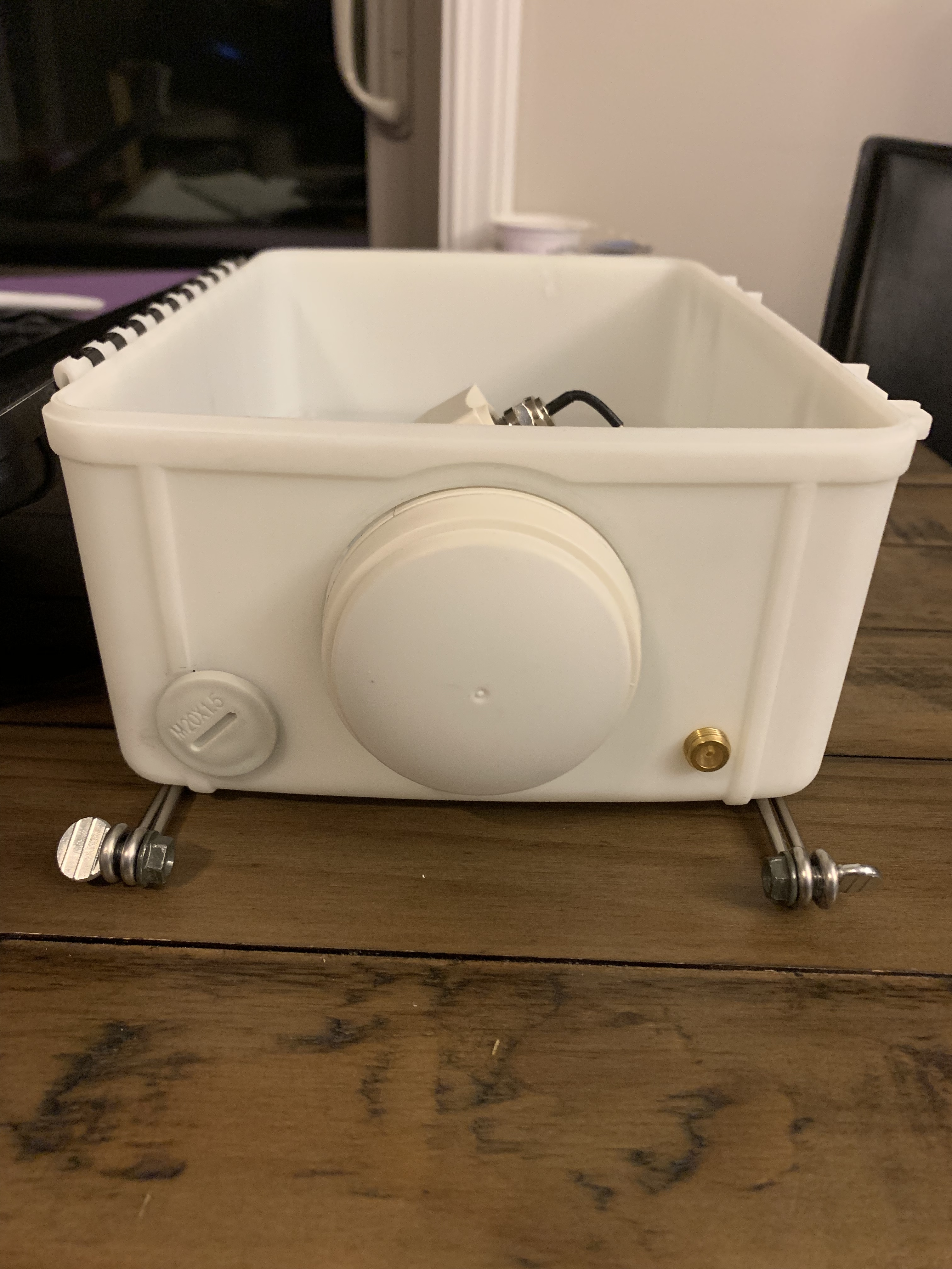
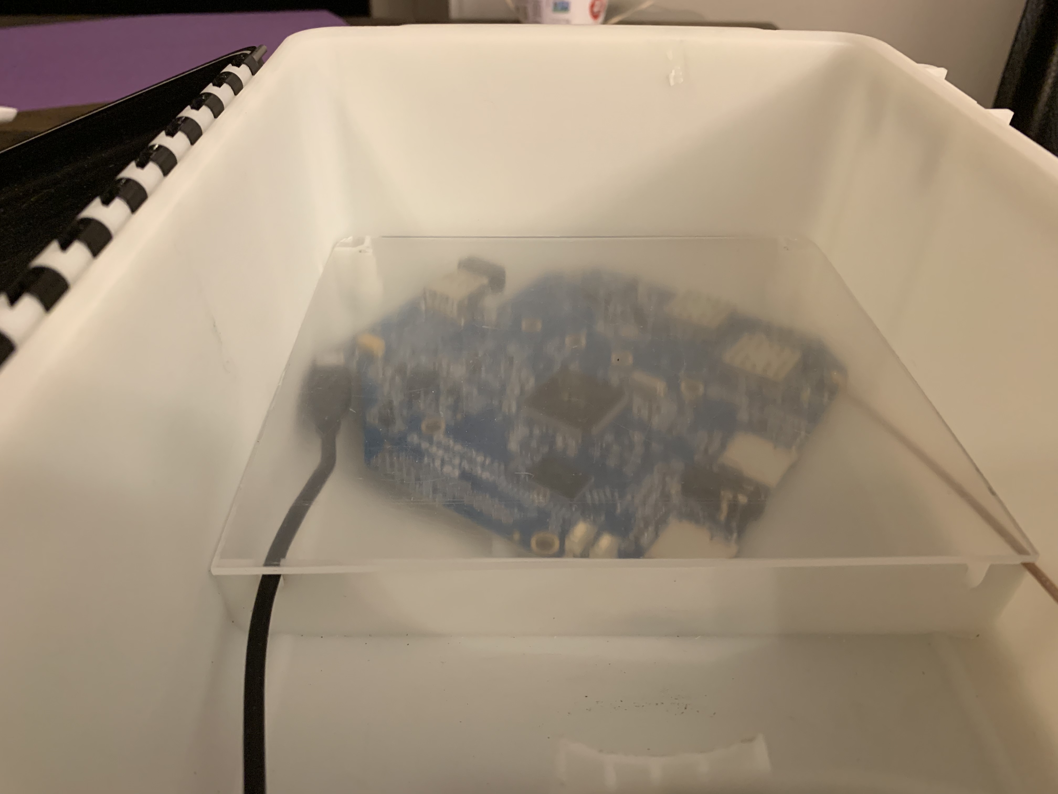
Another layer of plastic definitely attenuates the signal. This is a good idea for stability purposes and also to remove an additional part from the assembly (the LNB holder). But in order for this to work, the LNB would need to stick out of the end of the box.
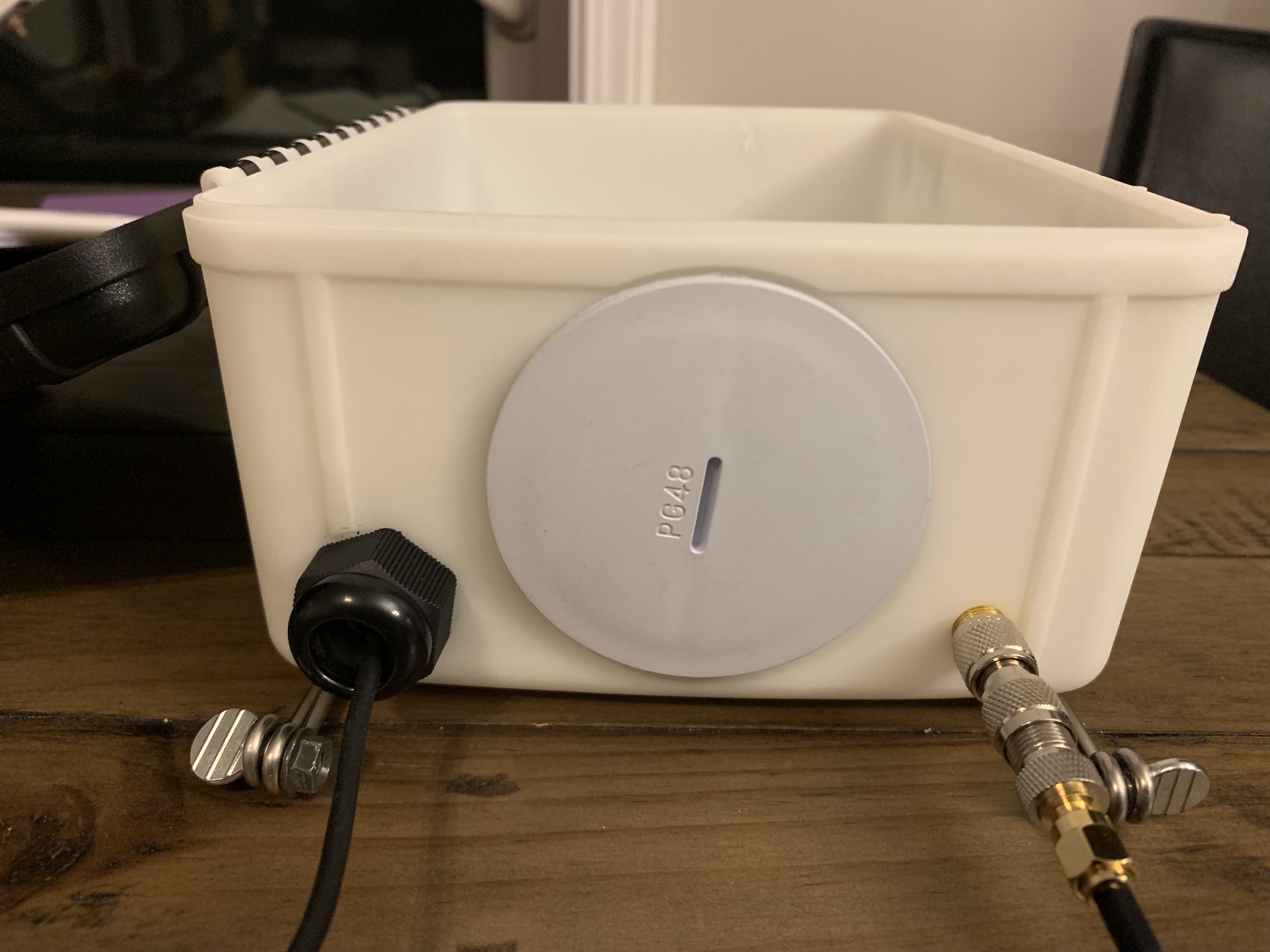
Yeah, that is an option. But I’m hoping for something that doesn’t appear too hacky. I know this case won’t be the most elegant of enclosures, but bolting parts on willy-nilly makes it a harder sell for non-hobbyists.
We’ve had it running inside of a clear, greenhouse-like container for months on end. 120F/50C operations were fine, but I can’t vouch for anything higher. No matter what the enclosure needs to be white or light grey.
I’m clearly missing something here. My experience with LNB’s for TVRO is that the drive from a LNB is substantial, currently I have a 40m co-ax between my satellite receiver and the LNB.
So rather than weatherproofing the unit mount it away from the LNB in a dry location ?
If my unit - which seems to be coming on a three legged donkey ever arrives I’ll comment further.
I think the idea @Syed is working on here is to be able to sell a unit that can all fit in a weather-resistant carry box and be easily put together in the field, such as in the parts of a country where there is no phone nor internet easily available.
Blockquote I’m clearly missing something here. My experience with LNB’s for TVRO is that the drive from a LNB is substantial, currently I have a 40m co-ax between my satellite receiver and the LNB.
So rather than weatherproofing the unit mount it away from the LNB in a dry location ? />
I believe what you have stated is a good case for experimenting, and a number of us have done just as you said, with good success. @kenbarbi and myself, @maxboysdad both have units mounted indoors, and are running a length of RG-6 Quad cable to the outdoor LNBF. Ken’s is 500 feet from the LNB. Mine is about 40 feet from the LNB. Both units work fine that way.
I’d say that 500ft is pushing it. After all we are talking about signals up to 1Ghz and RG6 is not ideal. In the UK WF100 is the most popular cable for sattv enthusiasts although the commercial installers like shotgun cable.
I’d have thought a two piece design would be best for alignment featuring a small dish. Squarials proved too expensive to make and currently LNB’s are dirt cheap and offer amazing performance over what we had 20 years ago. I’m on the edge of a footprint so every little helps and for tv have a 1.8m dish where alignment is critical and the signal level changes as the satellites move around in their box.
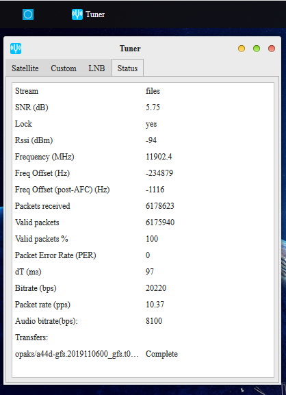
I’m using 500 ft of low loss RG-6 cable (the kind Comcast uses in buried installations) with my Maverick on an 80 cm offset FTA dish. Here’s my Tuner App data - -
Inside, at this time, I have a -94 dBm Rssi. At 1 GHz, standard RG-6 has about 6 dB loss per 100 feet. When I connect my Dreamcatcher outside, I get -74 dBm Rssi. An expected 20 dB drop - - usually my signal levels are more on the order of -102 dBm. All other signal parameters are the same - - especially the SNR. Ken
As there are no errors there is enough signal and signal quality. On my 40m run I experimented with a line powered amplifier half way and determined the results were better without it. This on TV as my dreamcatcher is ordered but not seen.
I’m not sure I understand the question, but as more information:
The LNB is outputting 75-ohms–no way around that.
The Dreamcatcher is expecting 50-ohms, but the losses from the mismatch are not huge.
From the u.fl/IPEC connector backwards (on the board), everything is 50-ohms.
I appreciate your time and explanation. The question arises from my having worked with transmitters a good deal of my professional life, and the importance of impedance matching. As we are working with just a receiver in this application, I understand the answer provided. Thanks!
My only concern is heat, midday in summer. It’s a shame it’s too big for a Rubicon - OpenH You could then have bonded the cpu to the aluminum.
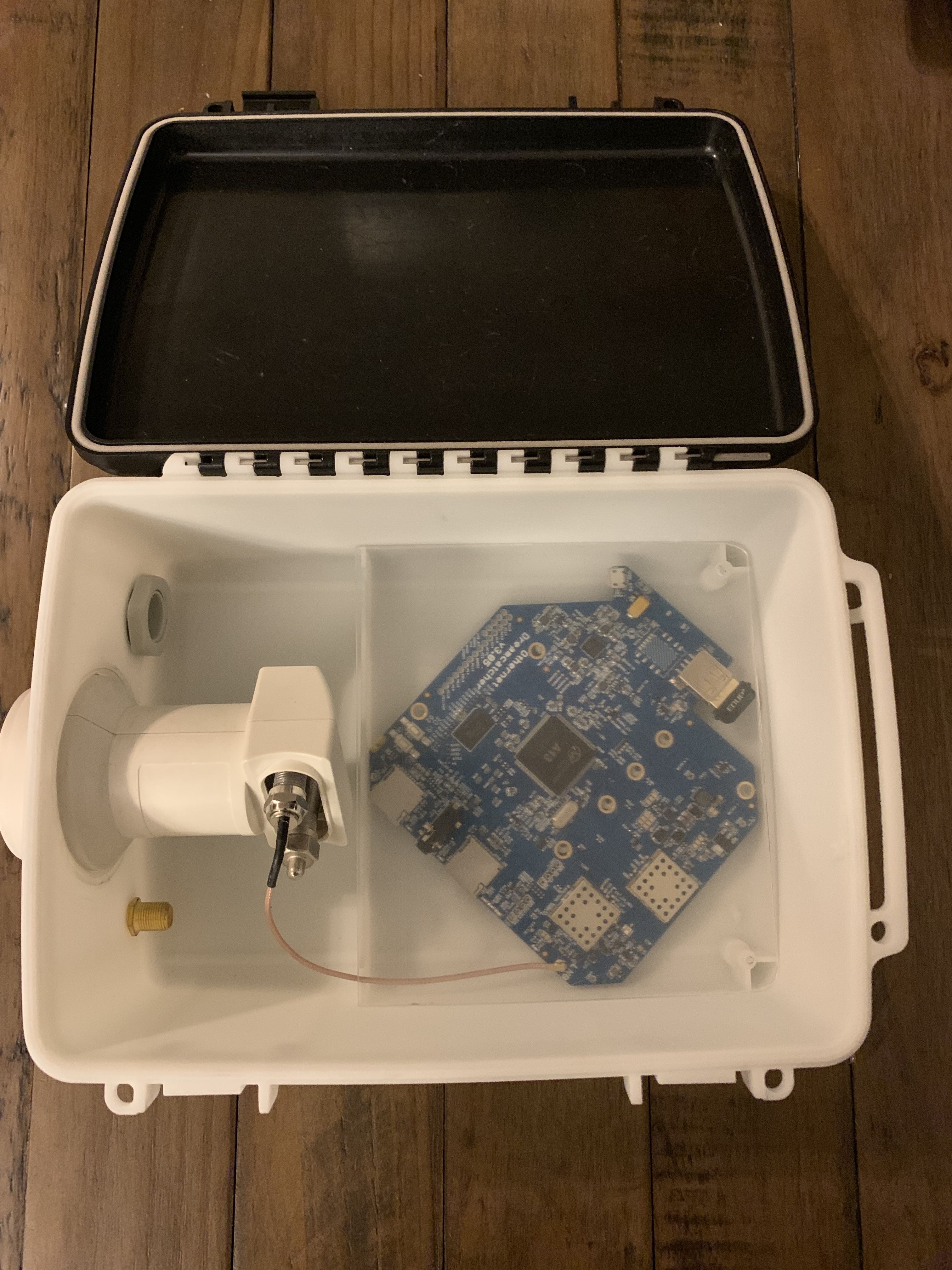
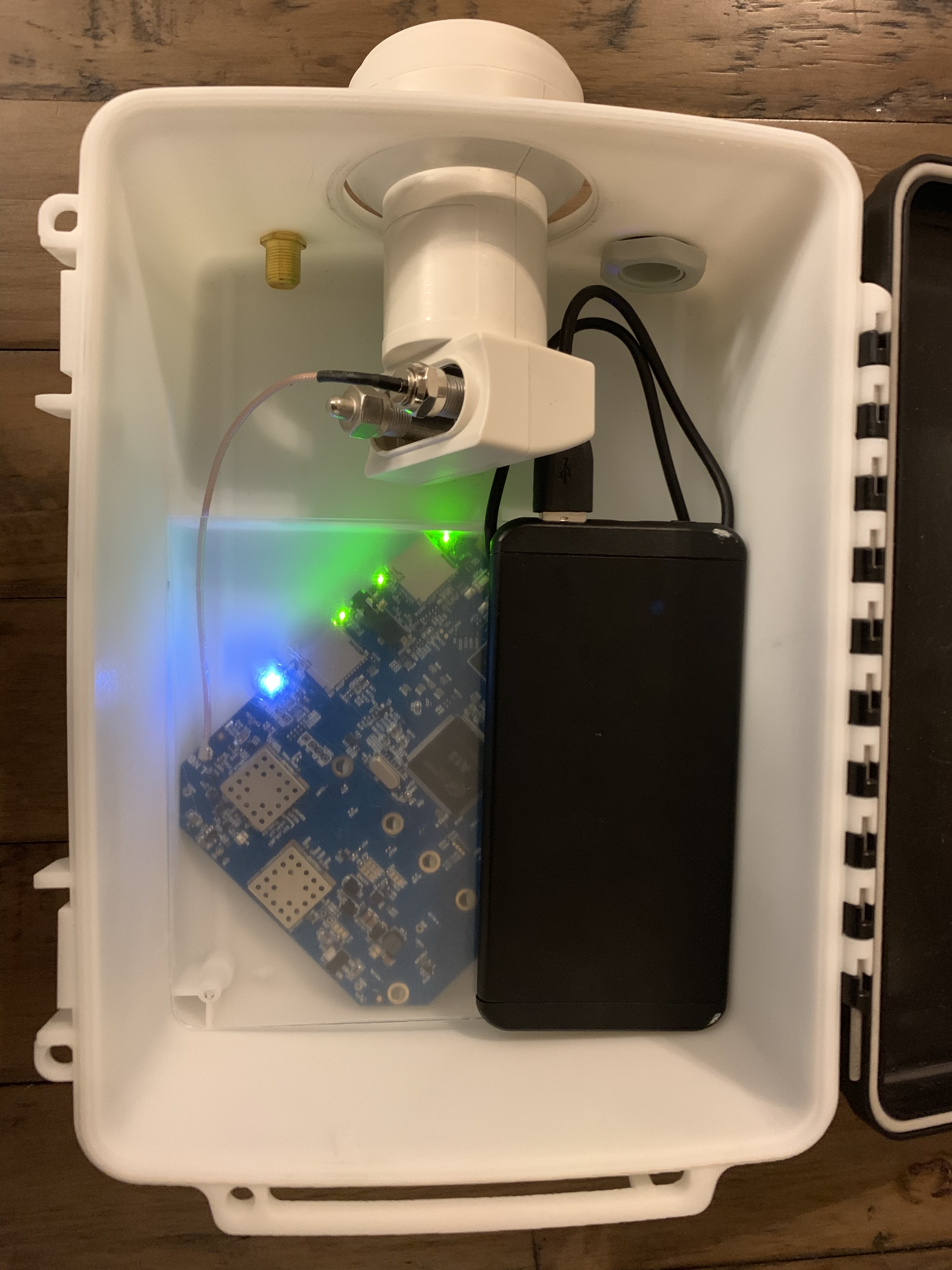
What purpose does the inner case serve? I’d be temped to leave it out so at least you have airflow inside the case and the slightly larger surface area for heat transfer.