I entered my email into the early orderer. I think it will match my needs for a signal generator (I only need it up to 2400mHz) for now… but it will match well with my rf explorer spectrum analyzer.
2 Likes
yes, it should work on any distribution - for now I will be releasing versions for 32-bit(x86)/ 64-bit(amd64) linux (any distribution) and for 32-bit ARM (like Raspberry Pi and Dreamcatcher).
edit: morfeus tool for windows(32 bit and 64 bit), linux(x86 and x64, any recent distribution), and linux-arm (32 bit, like raspbian on Raspberry PI and Armbian on Dreamcatcher) is now released and available on archive
6 Likes
Zoltan, Thanks! Yes, in RF, just about everything is a compromise. And, yes, size, power consumption, noise, spurious products, etc. are all a problem.
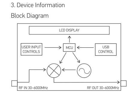
The beauty of moRFeus combines three building blocks that are often together: 1) LO synthesizer, 2) Mixer and 3) Controller.
BTW, here’s why I was asking if the LO could be swept:
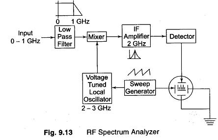
The Fundamentals Of Spectrum Analysis
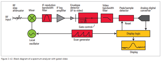
Keysight Technologies - Spectrum Analysis Basics
How much of the back-end can be done with a Software Defined Radio? GNU Radio?
How about one that has a narrow filter, a high gain LNA in front of it? What can you do with an SDRx and a few more components available on E-bay? Is the IF filter narrow enough?
–Konrad, WA4OSH
2 Likes
How about a transverter for the microwave bands?
moRFeus is a fundamental building block here too…
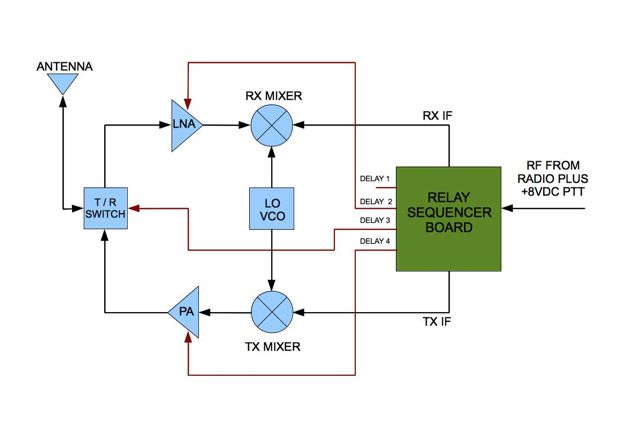
VK2AWX: What Is A Transverter? Part One
–Konrad, WA4OSH
2 Likes
Interesting device at an interesting price, especially if/when it can function without a PC hooked up, if I’m understanding correctly?
1 Like
if you referring morfeus, yeah thats correct. we developed a custom FW which drives everything in a standalone way (buttons, lcd, mcu, rf parts all in one device)
1 Like
- Working on this - thanks for pointing it out.
I’ll provide more clarification on the datasheet regarding the values in the Mixer Performance chart. Thanks for pointing that out - those columns could be defined better. .
1 Like
@unixpunk You are understanding correctly. Complete field-level operation. No PC needed. There’s an LCD display and button interface for controls.
1 Like
Excellent, thanks!
1 Like
Forget to mention that we have improvised a “satellite emulator” by daisy chaining a DC3v02Q and moRFeus:
2450 (LoRa) + 4600 (DC up converter) + 4650 (moRFeus up converter) = 11 700 MHz
This could be picked up easily by the LNB, dummy packets received at strong SNR. Of course this running massively out of spec of the moRFeus mixer and baluns, but still it deliver something like -90…-100 dBm signal level at 11.7 GHz (our spectrum analyzer stops at around 6 GHz so this is just an estimate)
This all done with “improvisation”. I bet that using a few IF amplifier and filters can easily pump up the output power by 20…30 dB. Theoretically the max frequency is 13.250 GHz (or adding a third moRFeus to expand the range but that case amplifier stages and filters are mandatory due to the extreme high loss).

4 Likes
Did you try disconnecting the last piece in the LoRa->moRFeus->moRFeus chain to see if it would pick up without? Those LoRa radios are so sensitive that they could probably pick up a leaked signal.
Nice catch! The LoRa freq (IF1) on the TX and IF2 on the RX is purposefully mis-tuned, so they cant pick up each signal.
Also it can seen nicely that moving the LNB or putting some lossy material before the LNB horn is degrade / influence the SNR, so the LNB picks up the signal.
More over I was very skeptical in the beginning so checked the LNB output by a spectrum analyzer while emitting CW signal from the SX1280 side, it was very weak but showing up in the spectrum where expected.
2 Likes
In the above picture is the DreamCatcher 3 in transmit mode?
Since the DreamCatcher 3 can receive LoRa signals at 950MHz, do you use moRFeus to down-band the 2.4 GHz LoRa from an SX1280 for a board tester? I don’t get why you need the MK1-PLL. Why not an attenuator pad and DC block into the DC3 DUT?
–Konrad, WA4OSH
Can you give us a few advance hints on the production schedule ?
Production is done. We have 100 units in house tested assembled ready to ship. Initial orders from Crowd Supply (launching today) will ship starting April 2 and once a week through the campaign. Units beyond 100 will ship with 30 days of the close of the campaign, but it’s highly probable those will ship sooner than we’re saying.
3 Likes
Is there a recommended time from start-up for the tcxo to stabilize? Assume starting at 25 C / 75 F.
My best guess is somewhere 1 msec or less. This is not oven compensated (OCXO) but temperature compensated (TCXO) oscillator. Those modern reference devices usually have a tiny mcu inside and a temp-freq lookup table and compensating the frequency “on the fly” as temperature changes (as far as I know).
I checked the datasheet for you but the manufacturer doesn’t state anything about such settling time.
and a good reading: TCXO Temperature Compensated Crystal Oscillator » Electronics Notes
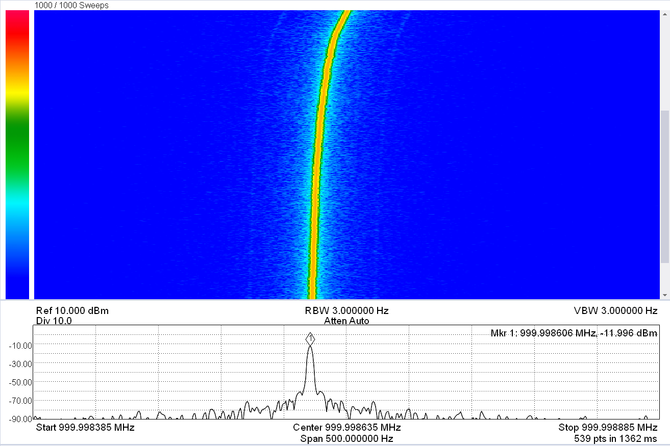
measured: it took the TCXO 5 min to “stabilize” after 29 Hz drift (0.029 PPM drift) at 1 GHz. This can be interesting for ultra narrow band applications like WSPR, else this is quite irrelevant. I guess this is so tiny drift that out of the control loop of the TCXO. Possibly has connection with thermal warm up after start.
(made this test without the aluminum case now)
BTW the measured precision was 1.4 PPM at room temperature, which was instantly available after start.
span: 500 Hz
4 Likes