Increasing Gain with 15-degree Cone

I received my Dreamcatcher last week.

First, thanks to Ken Barbi and everyone who contributed to the Dreamcatcher User Manual. It resolved all of the potential sticking points during initial setup and operation (“not enough sessions”, etc.).

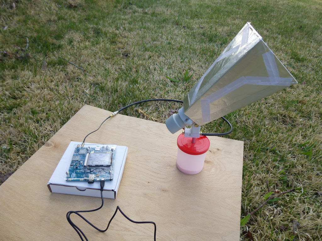
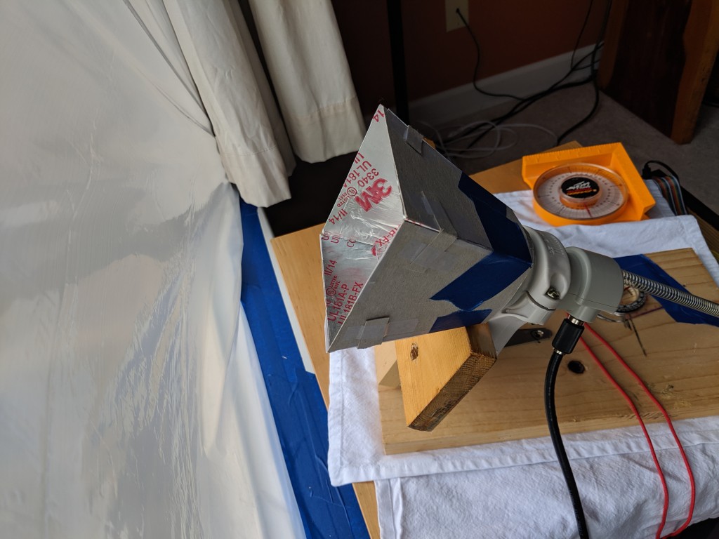
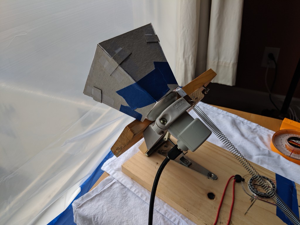
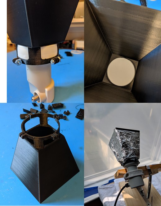
Based on comments in the manual and the forum, I was hoping to use the Dreamcatcher indoors, so I knew that I would likely need supplementary antenna elements or a replacement antenna. I decided to build a feedhorn supplement based on the dimensions used by thomslik earlier in this thread, but also using different construction materials. A photo of the interior of my feedhorn is attached. Note that I have not removed the plastic cover of the Maverick LNB.

Construction
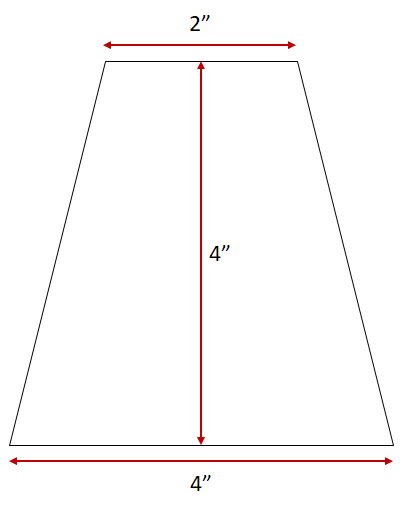
The dimensions of trapezoid elements are 5.72 cm x 12.7 cm x 22.86 cm (2.25 in. x 5 in. x 9 in.). Note that the 22.86 cm (9 in.) dimension is the normal distance between the parallel sides of the trapezoid and not the length of the long edges of the trapezoid. The elements are made from non-corrugated cardboard (from cracker/cookie boxes or frozen pie boxes). The elements are covered with kitchen aluminum foil, and the foil is secured with Scotch tape. I made an effort to insure that virtually all of the tape is on the exterior of the feedhorn in order to avoid any unwanted/unexpected dielectric effects.

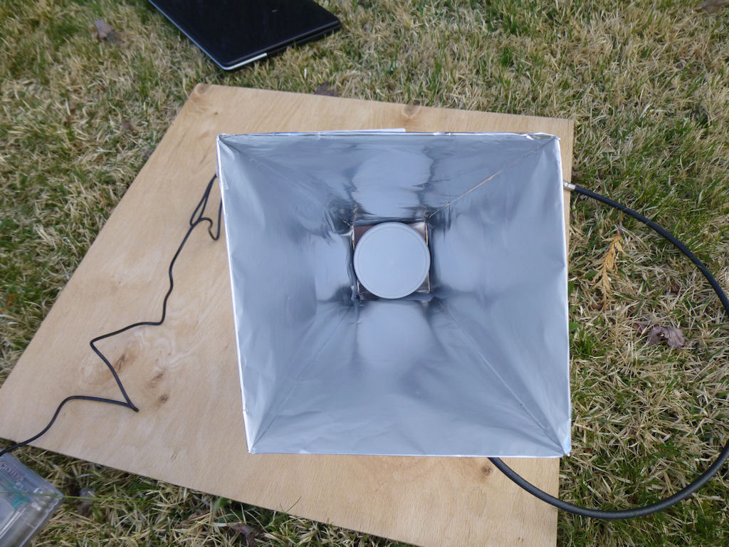
The feedhorn also has a base plate which is 5.72 cm (2.25 in.) square plus two flaps on opposing sides that extend approximately 2.5 cm (1 in.) at a 90 degree angle. The flaps make it easier to connect and tape the base plate to the trapezoid elements. The base plate is made of remnants of an aluminum shield from an old Ethernet router. The thickness is less than 1 mm (1/32 in.). The base plate has a roughly circular hole to accommodate the plastic case of the LNB. One side of the base plate has a cut in the middle in order to permit placement of the base plate on the LNB.

After all elements were completed, the trapezoid elements were connected with packing tape. Again, care was taken to keep the tape-free sides on the interior of the feedhorn. The feedhorn was then mounted to the base plate with packing tape. A connectivity/resistance check was then made to insure that all sides and the base plate had a good electrical connection. If you look closely at the photo of the interior of the feedhorn, you can see in the upper right quadrant that there is a gap in places between adjacent trapezoid elements (these were the last elements connected together). This is why it is a good idea to use a conductive base plate if you use this construction approach.

Testing
In order to get a sense of the feedhorn improvement, I made a point of conducting my tests in as close to the same conditions as my initial testing of the Dreamcatcher last week (same time of day, same location, guaranteed clear view of the satellite, same weather conditions, etc.). I used a 1 meter (3 ft.) length of RG-6 cable to connect the antenna to the Dreamcatcher. In initial tests with no feedhorn, the SNR had an extreme of -10.0 dB and had an estimated average of about -11 dB over the span of a half hour. RSSI ranged from -76 to -78 dBm. With the feedhorn, RSSI was in the same range, but the SNR improved to an extreme of -5.75 dB and an estimated average of about -6.75 dB. So this particular feedhorn yields an improvement of approximately 4 dB for SNR. So much for the ideal conditions tests.

When I tried to use the Dreamcatcher inside the house through a window with just the Maverick LNB, I struggled to receive any packets at all. I don’t know the thickness of the glass, but it looks like it might be a double pane. The occasional packet would get through, but the SNR would be around -15 to -18 dB. With the feedhorn and good weather, I get good reception with an RSSI between -73 and -75 dBm and an SNR extreme of -10.75 dB with an estimated average of around -12.0 dB. I should note that from inside the house I have no choice but to point the antenna through tall trees which do not have any leaves yet. So it will be interesting to see how much reception deteriorates as the leaves come out in the next month.

This past weekend we had very heavy rain at times and minor local flooding, so I got to see performance under poor conditions with the feedhorn indoors as well. Rain was sufficiently heavy at times that lock was lost for several minutes. If rain is light to moderate, the unit is generally able to keep lock, even when there is some water on the window surface.

Lessons Learned
I would not recommend using such a stiff type of aluminum for the base plate if you use this construction approach. I had to put the plate through some severe deformation in order to get it onto the plastic cover of the LNB, and it is a wonder the plate did not break. I would recommend using the same non-corrugated cardboard and aluminum method used with the trapezoid elements instead, or come up with a more flexible design yourself. I would also put flaps on all four sides of the base plate, so it will look like a fat plus symbol before mounting.

1 Like

What are the dimensions of the mouth of the extension?

12.7 cm (5 in.) per side. The photo will give a better sense of scale. I could only include one photo in the first post.

i obtained similar results using a far less elegant wire mesh horn.

How is the wind loading on the wire mesh? Does it wobble in the wind at all? How small are the squares on the mesh? About a centimeter?

The wire mesh designs also have an advantage over my approach with regard to the skew scale (the one above the -20 to +20 range): You can’t see it at all with my approach whereas you can through the wire mesh. I have no idea if I screwed up the skew when putting the feedhorn in place.

from my post 3d ago in this thread: “12.5mm wire mesh 10x20x5cm horn on the LNBF”

mesh horn did not wobble during recent wind storm. it’s a pressure/friction fit to the LNBF using the slight gap between the feedhorn cover and the body to ‘click’ into place.

reception seems mostly independent of weather conditions now.

I went through the forum archives, and collected (most of) the horn/cone creations along with brief construction details, and sorted them by nominal performance.

Othernet_Reception_Enhancement.pdf (569.4 KB)

Will

3 Likes

I experimented last night, and made a small horn out of cardboard lined with foil tape… 2" small opening, 4" large opening, but only 4" long vs 8" long. Saw 4-5 dB improvement. The shorter length makes things a little less unwieldy.

1 Like

Would you happen to have a picture?

That matches my cut down ‘solo’ plastic cup. I hope that could be incorporated into the case of the next dreamcatcher.

Yeah, we are definitely going to leave some room for extensions. I was hoping that we did not need to leave an additional 4-inches, though. But 4 dB improvement is huge.

Hey, Will, this is great. Send details & pics. Sounds similar to my collapsible drinking cup. Ken

Here are some pics. I made the template in powerpoint (a decent tool for quick templates, you can edit the size of shapes directly in inches and they print correctly - you don’t need formal CAD for everything!) And then I cut out four of the trapezoids on the sort of cardboard like the back of a legal pad. Lined each piece with Aluminum duct tape, and then assembled as shown.

One thing I note, which I haven’t entirely sorted yet… when I put the horn on with the original aiming, I get some benefit. If I re-aim, I can get even better SNR. For instance, I was running let’s say at -14dB SNR. When I added the horn, with the same aiming, I got let’s say -12dB. When I lowered the elevation somewhere between 10-15 degrees, I got the 4-5dB improvement, and now hover around -9dB. So at my latitude, the bare LNB elevation is supposed to be 45 degrees. This 4" horn setup is slightly below 35 degrees, and I’m getting pretty great signal.

I found I can also accomplish the same gains by tilting the horn on the LNB, leaving the LNB at 45 degrees elevation, but tilting the horn down 10 degrees or so.

This is indoors pointing out of a window, so there may be secondary effects I haven’t picked up on yet that are making these side-effects present themselves. But if you just do a re-aim after installing the horn, and ignore your instruments and go solely by SNR, then I guess it doesn’t matter.

In playing around, I tried just putting a single rigid metal sheet above the horn, and could see 1-2 dB improvement in SNR with essentially only 1 of 4 walls. Unsure if it’s blocking noise or reflecting signal.

I don’t think you need 4 inches extended beyond the plastic shield of the lnb. My aluminum covered ‘16 ounce cup’ is a total of 4 inches that starts at the F-terminal and sort of provides both side lobe shield and focusing cone into the lnb. I end up with a SNR that varies between -11.75 and -12.75 , and it is much more forgiving to point then the bare lnbf.

Lesson learned… Don’t leave the bright aluminum in the sun. It has good ‘absorption’ of solar heat energy BUT poor ‘emissivity’ . It needs a good coating… (like white paint) to keep what’s near it cooler.

I don’t know all the math on coatings… but people with airstream trailers have learned to paint some of the exposed shiny metal to keep things cool.

So… if you make a aluminum ‘cone’ … make sure you coat it so it doesn’t excessively overheat the stuff inside.

uhh i hope you didn’t melt anything

Yes… the plastic solo cup ‘deformed/melted’, the aluminum foil was trying to hold it’s own… had our first sunny day.

Had a Mechanical Engineer friend at work CAD me up a horn with a mounting clamp and nice fitting dimensions. I 3D printed it using PLA filament at home (would not sustain high heat outdoors, per recent posts, but ABS would). Roughly covered the outside with aluminum foil, and again seeing 4-5dB SNR improvements… and I would hesitate but say I was seeing closer to a solid 5dB SNR improvement. He made a slight detent on the inner face of the clamping ring, to catch the LNB at the intersection between the white cap and the beige body…where the draft-angles of the two plastic halves meet. Helps ensure orthogonal installation of the horn onto the LNB.

Now if I can figure out how to (cheaply) plate or paint it with RF reflective coating to move away from fiddly foil or foil-tape. I see RF paint for about $80/pint, oof. Any Elmers out there have any tricks?

How did you come up with the dimensions and angles for the waveguide extension?