@k5ted
certainly not as pretty as yours but DANG that thing rocks!
the “packet failure count” is due to me swapping antennae.
@k5ted
certainly not as pretty as yours but DANG that thing rocks!
the “packet failure count” is due to me swapping antennae.
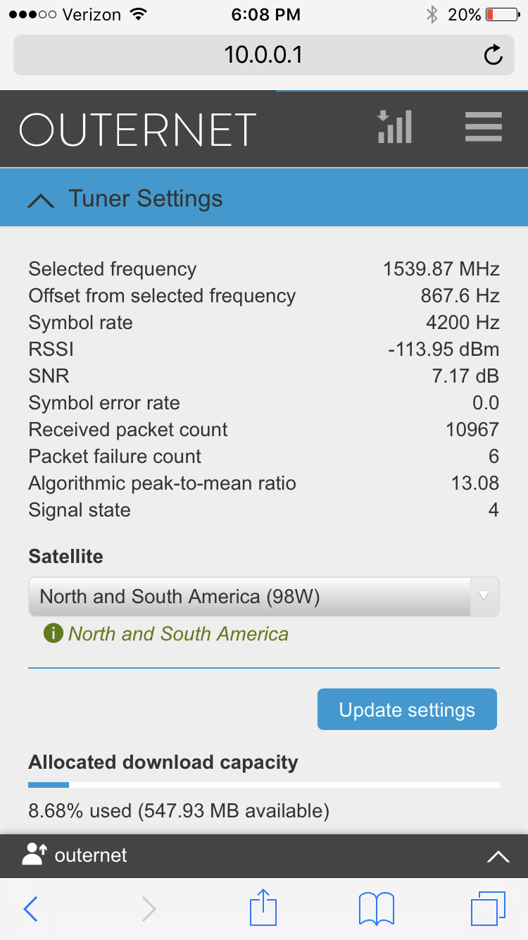
Still RSSI at -113 is a nice hot signal. That is 3db higher than I am at, and I also have a SNR of 7.
I am beginning to think the SNR out of the SDR decoder may have some limitations.
-C
roger that. I had an snr or 9 with an rssi of -111 earlier but I was holding the antenna in one hand and trying to do a screenshot one handed on my phone and missed it.
were your readings on the patch or on the paper helical?
on my KIT patch antenna the rssi is “cooler” than when I use the paper helix.
so for me at least my rssi is better while using the paper helix. There are so many factors that come into play though.
I live in a completely RF quiet area. None of my ham gear is on etc. So my noise floor baseline is perhaps a bit more stable? who knows
for instance, my noise floor right now for 1.5ghz is at -113
I would have to hook up the laptop to the patch and run SDR# to get a noise floor number. I am out of town so the only noise would be 300MHz down in 1.2GHz. Maybe when I have finished logging a few days of RSSI/SNR data I will pull the skylark apart and check the noise floor.
Those numbers above are on the patch antenna with outernet PA and SDR dongle. My receiver is sitting on my kitchen table and pointing out a sliding glass door. I had it outside but I didn’t get any better numbers there.
-C
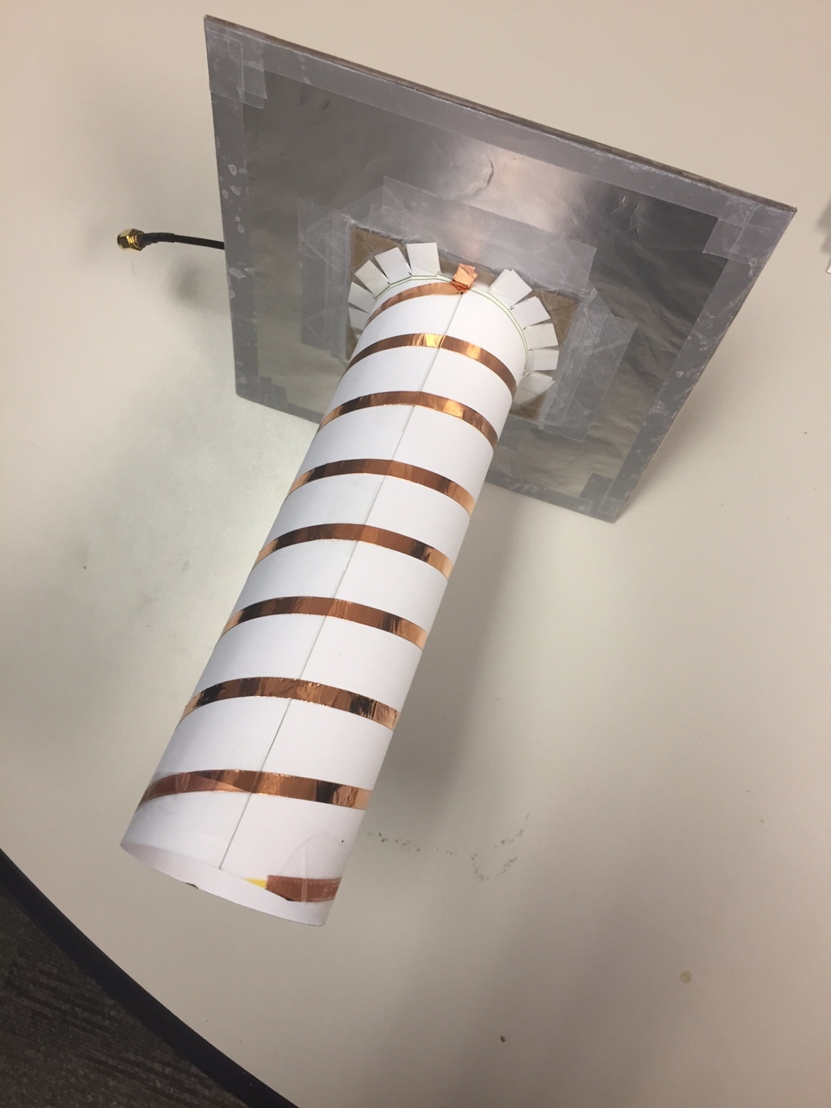
I rolled up a double helix. Man, it was pretty…
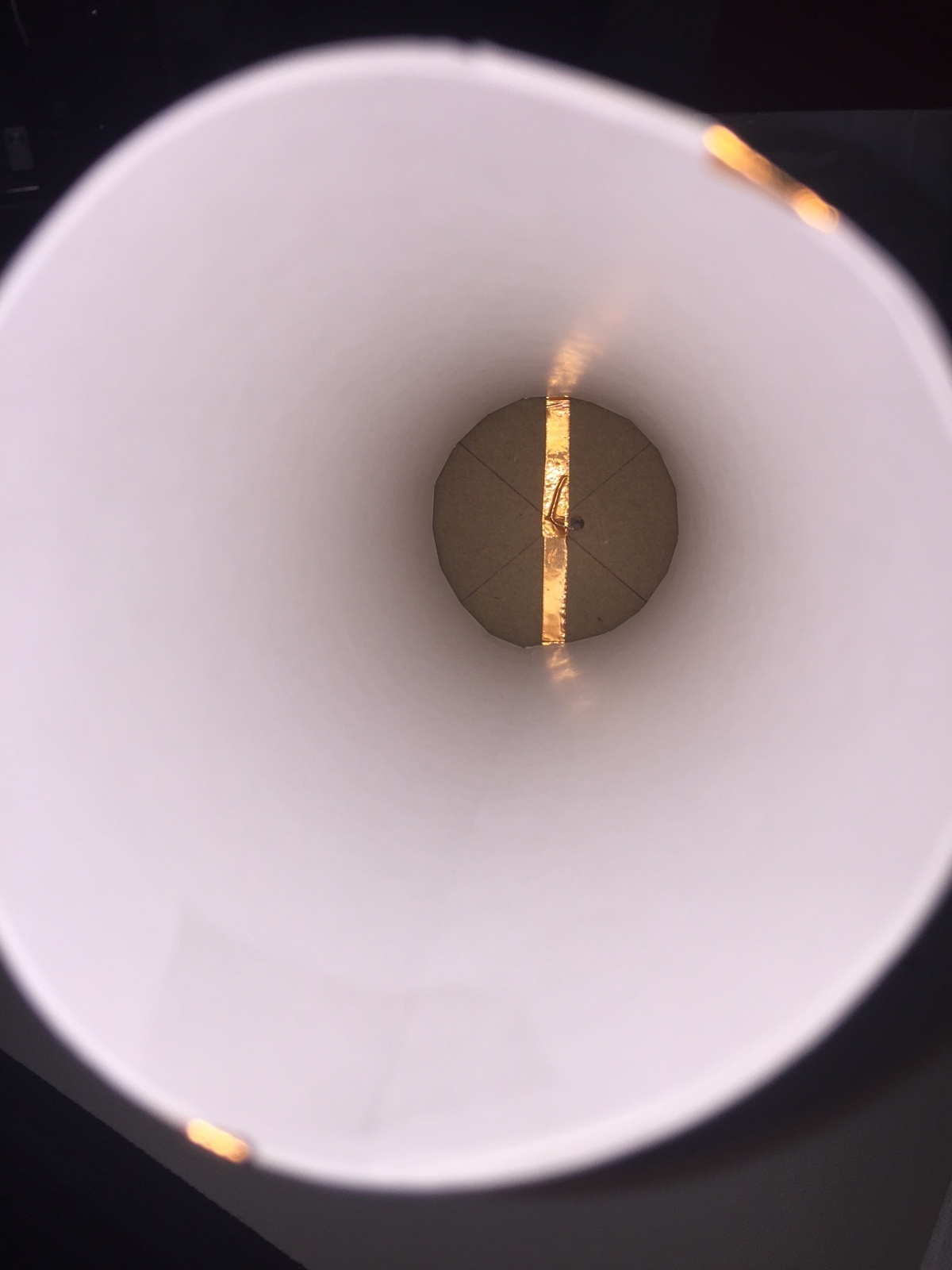
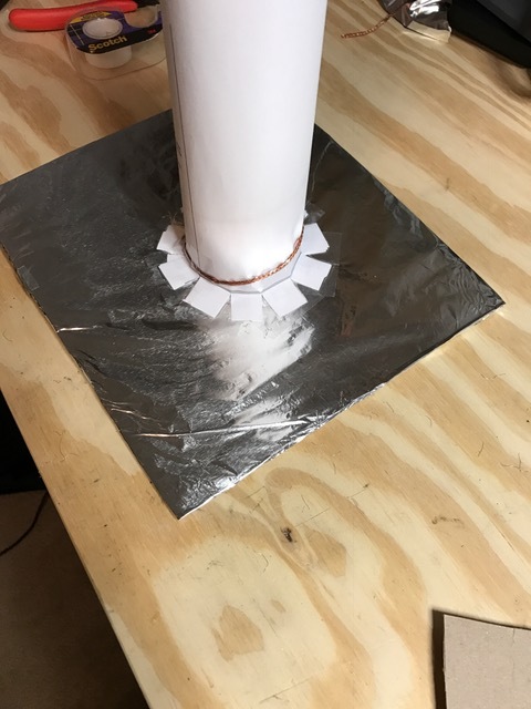
There is no real construction data for this on the web other than some claims of awesomeness and a guy wrapping electric fence wire around a Craftman ratchet handle, so I followed the one video for the 5.8 GHz one and scaled appropriately, and used the matching/feed method described, that is, basically a parallel feed elevated a mm or so off the ground plane:
And, much as I anticipated, it was absolutely a failure. .021 SNR and -124 RSSI. I’m not sold on feeding a probe with two signals that are 180 degrees out of phase, and coupled with the two intertwined helices, which cannot help but affect each other electrically…
Not giving up on the design completely, but still searching for some actual lab data that validates the concept
I’m about as ecstatic or what passes for that in me, to see that someone was able to replicate my creation with success. Looks like you have about identical performance. This is good news.
Honestly, the antenna is pretty badass! I didnt even have it sitting on anything stable. I just held it in my hand (im old and its cold as crap here so It was a quick test) and the snr lit up like a Christmas tree!
In all seriousness I can see this being mailed to folks all over the place or just some more illustrated instructions for them to make it at home.
Thanks for taking the time to do this.
I think the spiral could be made of thin strips of aluminum foil, overlapped to form a continuous conductor, taped to the paper. Haven’t tried that yet. Would make it even easier for it to be built with household items. The one thing that is not easy to procure is the SMA pigtail. It would have to be provided with the kit, or a suitable alternative feed method developed.
so I was just working on that pigtail thing. I am going to try a couple different “things from the house” approaches and see how it works. alligator clip to go on the outside of the sdr sma and a small “pin” (wire) that can be inserted into the center socket.
you could use a small section of ladder line and two wire-nuts. or perhaps a paperclip broken in half to give two pieces of wire and use a clothes pin to clamp on to the sdr sma and the other piece shoved into the center socket
Was thinking along the lines of a length of 24AWG from a piece of CAT5 cable, long enough to do the helix and 1/4 turn match section, then right down through the hole into the end of the LNA SMA jack (LNA taped to the backside of the groundplane cardboard) and a short piece of same wire taped to the foil and down through the hole. wrapped around the threads on the jack.
damn good idea
The paperclip is good idea for the ground clamp. Land it on the top of the foil, then down through the hole and make a sort of “U” shaped pinchy thing to clamp on the SMA barrel. The SMA center pin is pretty small though, so the thin wire or wire with thin pin is a necessity.
This thing would actually be pretty sturdy if sprayed down with a couple of coats of polyurethane clear, then put under a radome or in the open after adding a another coat of that black sealant spray form the infomercial.
Maybe the kit should start including an SMA to BNC converter pigtail. Those BNC are much easier to work on, and to locate I would guess. Plus at 1.5G they have the same performance.
Oh and one other thought, have either of you made your helix’s in both right and left hand flavors? I know on my 7GHz microwave systems 90deg polarization can be as much as 12-15db down when crossed.
-Cecil
in this instance I have not made opposite polarization. but yes 90 phase difference should yield 12-15 down.
“typically” 90 degree phase difference should give you an average of 21 db isolation
Hi again Cecil - - I’m working my way down the Discussion Group posts.
Have you considered a Koch Curve Fractal antenna? I have a design in mind with a gain of the Patch, smaller foot print, and wider beam width. I’m starting to build it, but I don’t know how successful I’ll be. I will certainly share my results here.
Any thoughts on fractals? Ken
Outernet is RHCP. Helicals can receive both “vertical” or “horizontal” linear polarization equally well, but the “handedness” has to be the same or there will be serious rejection. In Outernet’s case as with all the Inmarsat antennas, right hand circular polarization is used.
Just mulling over the noise problems. I wonder if the decoder could be written to accept input from two RTL devices, one that would be the “main” receiver, and another cheaper one that would act as a “local noise” receiver, using a simple monopole antenna separate from the main antenna. The extra code would look at the local noise receiver and compare with the main receiver signal, and remove the local noise, leaving the cleaned up signal for the decoder to work with.
We have the same sort of thing in hardware that is used for phase cancellation of local noise in HF receivers. Should be able to happen in software as well. Thoughts?
effectively a diversity receive array with baseline comparison / rejection and quasi dsp cancellation, yes?